
Instrumentation Demonstration
What You Will Learn in This Chapter
Client education is the foundation of neurofeedback training, and this chapter shows you how to introduce clients to the process while building your own competence with EEG equipment. You will learn how to prepare a client, set up and operate EEG hardware and software, locate International 10-20 system sites, choose between separate electrodes and a full cap and between wet and dry sensors, prepare each site, and attach electrodes.
You will also learn to recognize a normal raw EEG, to create and control artifacts so that recordings and brain maps are valid, and to distinguish abnormal EEG waveforms from generally benign activity. Along the way you will review the descriptive terms and acronyms clinicians use to characterize rhythmic and periodic patterns.
BCIA Blueprint Coverage: This unit addresses III. Instrumentation and Electronics, E. Instrumentation Demonstration. It covers Client Preparation, Basic Set-up and Operation of EEG Equipment, 10-20 System Electrode Placements, Site Preparation, Elimination of Artifact from EEG Recording, Descriptive Terms, and Generally Benign EEG Activity.
Client education is the foundation of neurofeedback training (NFT). Professionals can explain core concepts, provide a road map of the NFT process, clarify their respective roles in the training process, and summarize clinic policies. The initial session provides an opportunity to address misconceptions about how NFT works and what the equipment does. Written informed consent is a contract that codifies the terms of your relationship with your client.
Applicants must develop competence in EEG equipment setup and operation. Demonstrations and hands-on training in didactic training programs provide many attendees' first introduction to instrumentation and software. The mentorship relationship builds on this foundation as applicants practice their growing skills on themselves and family members and friends. BCIA's Neurofeedback Essential Skills List provides a detailed checklist of the competencies that applicants need to master. This document serves as the blueprint for all our Demonstration units.
EEG equipment literacy requires that applicants understand how to measure the scalp, identify International 10-20 System sites, and attach electrodes. They must understand what a normal raw EEG looks like and gain experience in creating and controlling artifacts so that EEG measurements and brain maps based on them are valid. Finally, applicants must learn to recognize abnormal EEG waveforms and distinguish them from benign activity.
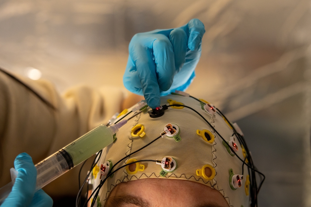
Graphic © Studio Cobalt/Shutterstock.com.

🎧 Chapter Lecture: Instrumentation Demonstration
Client Preparation
BCIA's Neurofeedback Essential Skills List provides an overview of client orientation. These include concepts, major stages, client role and responsibilities, equipment basics, and written informed consent for treatment or training.
Concepts
Explain neurofeedback, self-regulation, and operant conditioning of brainwave activity in the language your client will understand. Adjust the level of explanation to your client's education and experience. Educational handouts and videos like ISNR's Neurofeedback Overview can be invaluable. Hammond's (2011) What is neurofeedback: An update provides a helpful overview for your professional colleagues and the public.
Neurofeedback
Anticipate and proactively address common misunderstandings about neurofeedback. The equipment does not run current through your brain, does not change your brain, read your emotions and thoughts, or assess your intelligence, personality, or psychological health.
Emphasize that neurofeedback training (NFT) is based on neuroscience. Show pictures of a neuron and the human brain, and explain them in layperson's terms. Then introduce the concept of neuroplasticity:
Historically the brain has been seen as hard-wired, with each area having its own function. If that area was injured, its function was lost. Today the concept of neuroplasticity has replaced the hard-wired model. Neuroplasticity refers to changes in neural pathways and synapses which are due to changes in behavior, environment, and neural processes, as well as changes resulting from bodily injury. Neuroplasticity occurs on a variety of levels ranging from cellular changes to large-scale changes involved in cortical remapping. The role of neuroplasticity is widely recognized in healthy development, learning, memory, and recovery from brain damage. (AAPB, 2019)
Present the ISNR Board of Directors' definition of biofeedback (2010):
Biofeedback is a process that enables an individual to learn how to change physiological activity for the purposes of improving health and performance. Precise instruments measure physiological activity such as brainwaves, heart function, breathing, muscle activity, and skin temperature. These instruments rapidly and accurately “feed back” information to the user. The presentation of this information — often in conjunction with changes in thinking, emotions, and behavior — supports desired physiological changes. Over time, these changes can endure without continued use of an instrument.
Emphasize that neurofeedback is a drug-free, surgery-free behavioral intervention.
The goal of biofeedback is to increase your body’s ability to regulate itself. Self-regulation is the ability of your nervous system to respond adaptively to changes in your environment, both internal and external. (Khazan, 2019)
Self-Regulation
Explain that neurofeedback is a mirror that provides immediate information about specific brain activity to treat disorders or improve performance. NFT helps clients change brain patterns to achieve desired cognitive, emotional, and physical changes. While clients are not consciously aware of the neuronal changes, they often learn how successful self-regulation feels and can produce positive states in everyday settings.
Operant Conditioning
Explain that NFT utilizes operant conditioning to teach neuronal self-regulation. AAPB's (2019) description might be helpful:
Operant conditioning is a method of learning that uses rewards and punishments. The likelihood of a specific behavior is increased through positive or negative reinforcement each time the behavior is exhibited so that the client comes to associate the pleasure of the reinforcement with the behavior. Over time, the person learns to self-regulate their physiology without the need for a computerized biofeedback device, can perform the behavior outside the clinic, and can create clinical improvement associated with self-regulation.
Major Stages in Neurofeedback Training
Describe intake and assessment, what NFT sessions will be like, scheduling, expected number of sessions, cost and insurance coverage, home practice, and how you will continuously monitor their progress.
Client Role and Responsibilities
This stage is critical to NFT training success and client satisfaction. Emphasize that NFT resembles personal training for peak performance and that clients must be active participants in the learning process. NFT teaches self-regulation skills, and watching displays does not passively change the brain.
Describe the exercises they will practice outside of the clinic and why practice is important. Set expectations for practice time, frequency, charting, and accountability. The client's responsibilities should be spelled out in the informed consent agreement. Explain your clinic's policies concerning privacy, responsibility for payment, session reminders, rescheduling appointments, missed appointments, arriving late to appointments, and leaving sessions early.
Equipment Basics
During the first session, explain what the equipment does and how it works. This should include the purpose and steps in skin preparation, the function and safety of sensors (while avoiding the term electrode), the selection of site placements and steps in sensor attachment, the concepts of amplitude and frequency and z-scores, how to understand feedback displays, the relationship between the client's activity and changes on the feedback display, and what will be recorded during a session and how to interpret screens that monitor progress.
Written Informed Consent
Written informed consent is a contract between you and your client. State whether the NFT application is experimental or well-supported by peer-reviewed research. AAPB's Evidence-Based Practice in Biofeedback and Neurofeedback (4th ed.) objectively assesses NFT efficacy (Khazan et al., 2023). State your clinic's policies, including privacy, insurance, and responsibility for payment. Spell out your respective responsibilities as clinician or coach and client.
Explain that you cannot predict the number of training sessions your client will require, since each individual is unique. Instead, you will collaboratively assess client progress and the benefit of additional training sessions.
Clinical Application
A new client asks how many sessions she will need and whether her insurance will cover them. Because written informed consent is a contract that codifies your relationship, this is the moment to document your clinic's policies on privacy, payment, scheduling, and missed appointments. Explain honestly that you cannot predict the exact number of training sessions, since each person is unique, and that you will assess progress collaboratively. State whether the application is experimental or well supported by peer-reviewed research, drawing on resources such as AAPB's Evidence-Based Practice in Biofeedback and Neurofeedback. Handling these questions clearly at the outset builds trust and sets realistic expectations.
Key Takeaways
Client education is the foundation of neurofeedback training, and the first session is your opportunity to explain concepts, outline the process, clarify roles, and review policies. Describe neurofeedback in plain language as operant conditioning of brainwave activity that helps clients learn self-regulation, and address common misconceptions directly. Emphasize that clients are active participants whose home practice and consistency drive success, since watching displays does not passively change the brain. Cover the equipment basics so clients understand skin preparation, sensor function and safety, site selection, amplitude and frequency, and how feedback displays relate to their own activity. Written informed consent is a contract that spells out mutual responsibilities and clinic policies.
Check Your Understanding
- How would you explain neurofeedback, self-regulation, and operant conditioning to a client with no science background?
- Why is it important to emphasize that the client is an active participant rather than a passive recipient?
- What common misconceptions about neurofeedback should you anticipate and correct during the first session?
- What elements belong in a written informed consent agreement for neurofeedback training?
- Why can you not promise a client a specific number of training sessions?
Basic Set-up and Operation of EEG Equipment
BCIA's Neurofeedback Essential Skills List identifies several competencies in EEG equipment setup and operation. These include measuring the scalp and locating each International 10-20 system placement site; correctly preparing the scalp and ears and attaching electrodes to assessment sites or attaching an electrode cap for a full-cap qEEG; applying conductive gel to the sensor; making correct hardware connections to the computer; and making correct electrode connections to the EEG amplifier.
They also include performing all steps required for multi-channel or qEEG recording, such as checking impedance, performing a tracking test, detecting and removing artifact, and obtaining eyes-open and eyes-closed data; performing a continuity test to ensure electrode integrity; identifying and removing or controlling sources of common artifacts that contaminate the raw EEG signal; and troubleshooting common equipment failures following the manufacturer's recommendation.
Finally, they include demonstrating a basic understanding of multi-channel and qEEG assessment reports as well as components of qEEG databases (absolute power, relative power, phase, coherence, comodulation, and z-score comparisons); showing how to start the software, set NFT protocol parameters, and run basic feedback functions; demonstrating how to set initial training thresholds and adjust as needed; and describing how to mitigate the transmission of infection, including scalp measurement, skin preparation, electrode attachment, application of gel, and cleaning of cables, sensors, caps, and exposed surfaces.
Proper Electrode Attachment and Location of 10-20 Sites
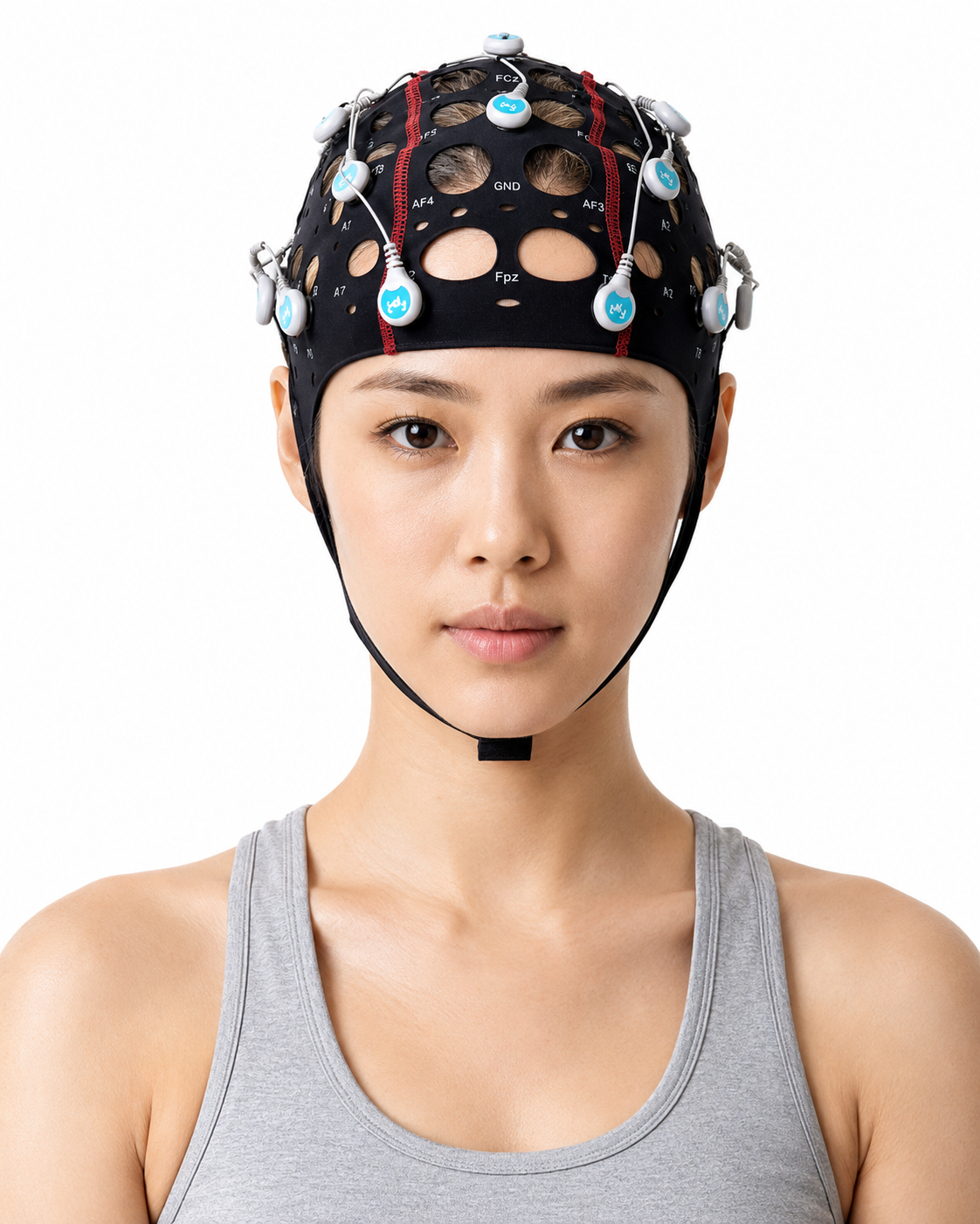
Review of 10-20 Site Locations
The International 10-20 system is a standardized procedure for placing electrodes at reproducible sites across the scalp. The classic array locates 19 recording electrodes on the scalp plus two auricular reference electrodes, for 21 standard positions (Acharya et al., 2016), with a separate ground. A scalp-detectable signal requires at least about 6 cm2 of cortex to be synchronously active, so no electrode reports a neat patch of its own: because current spreads through brain, cerebrospinal fluid, skull, and scalp before it reaches the sensor, adjacent electrodes sample overlapping cortical territory. That spread, called volume conduction, is also why the site where a signal is largest can lie some distance from the tissue that generated it.
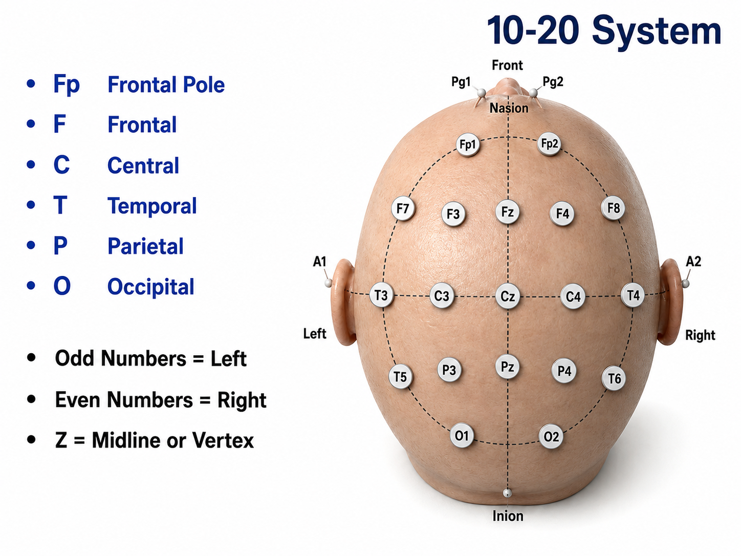
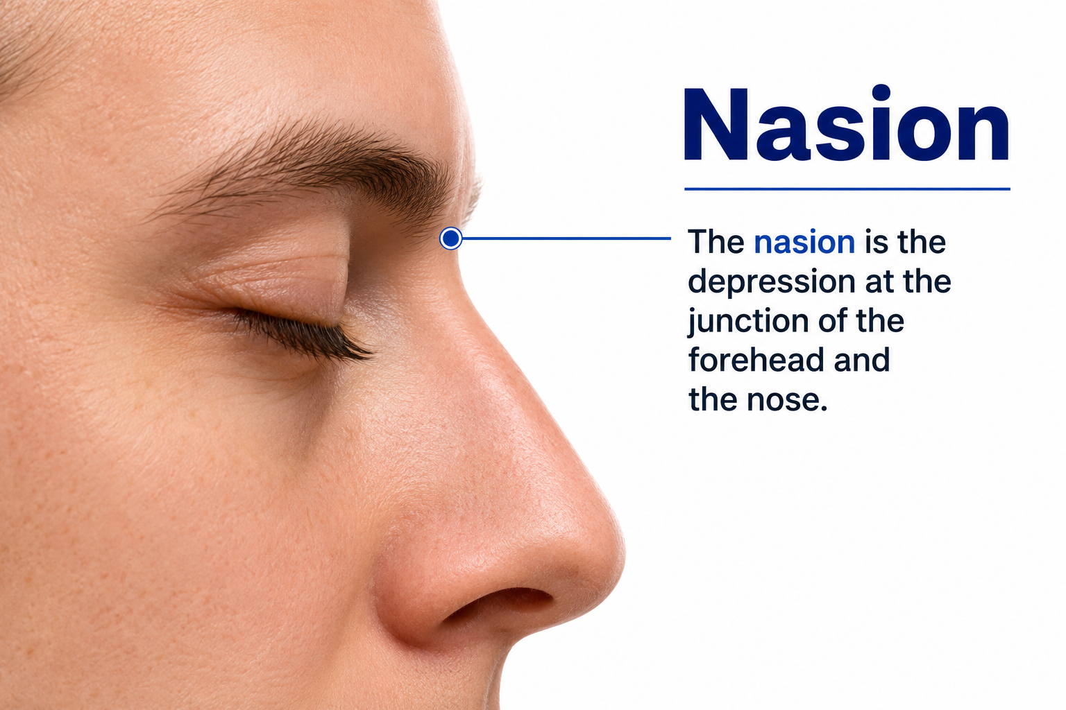
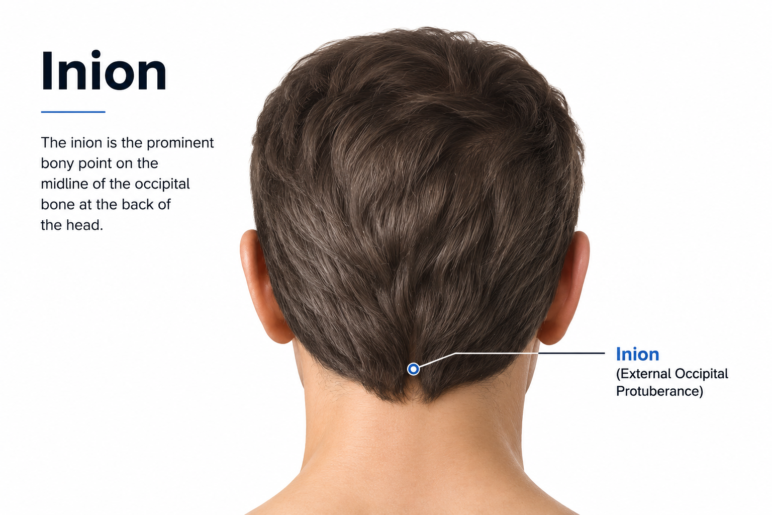
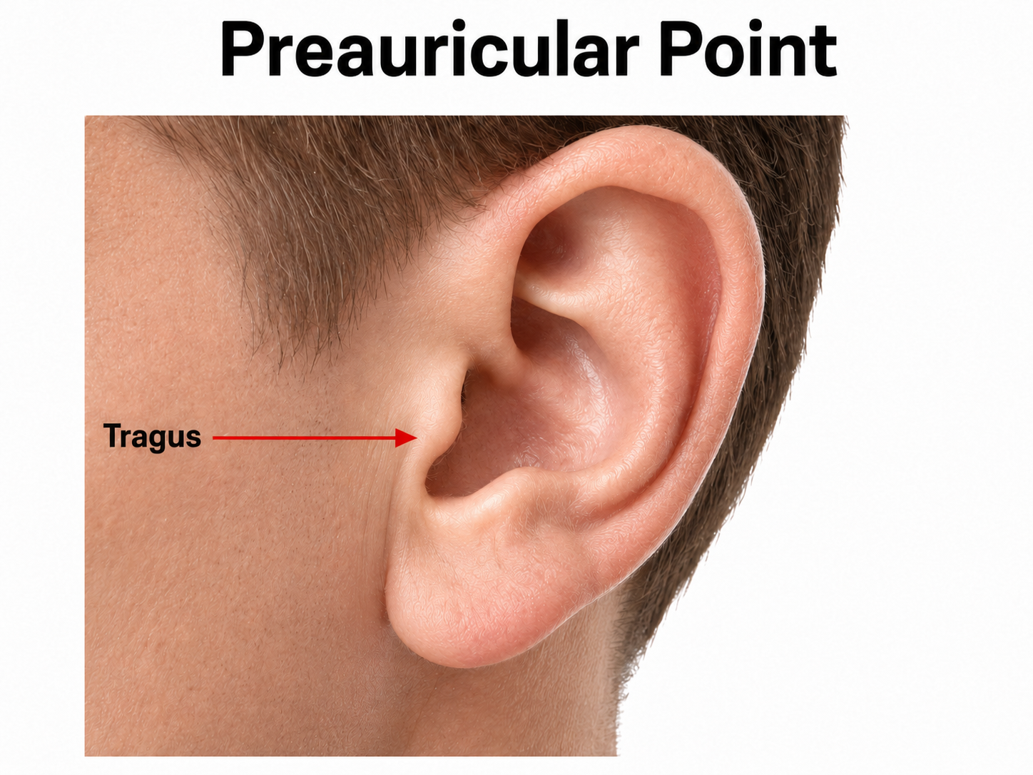
The International 10-20 system calculates the distance from the nasion to the inion and from the left preauricular notch to the right preauricular notch. The 19 active electrode positions are found taking either 10% or 20% of these distances. Check out the YouTube video The International 10-20 System. Four crucial landmarks are the nasion, inion, preauricular points, and vertex.
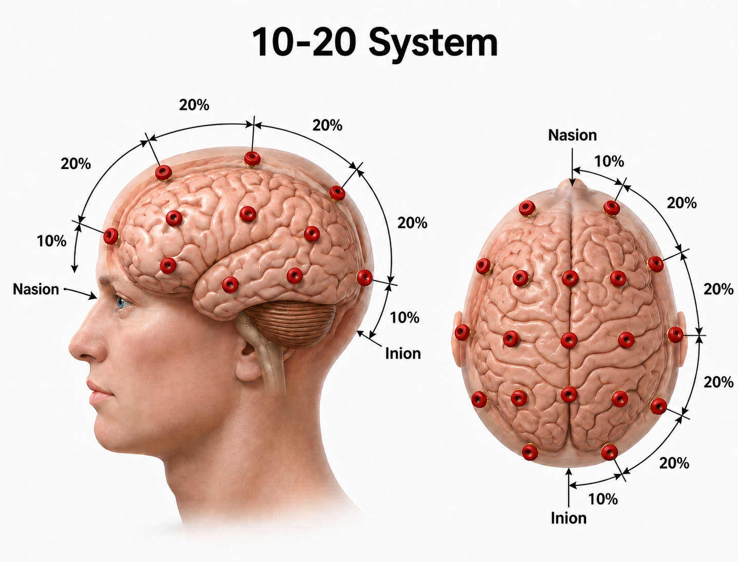
We adapted this graphic from © Alila Medical Media/Shutterstock.com.
The nasion is the depression at the bridge of the nose.
The inion is the external occipital protuberance, the bony prominence in the midline at the back of the skull along the occipital ridge.
The left and right preauricular points are slight depressions located in front of the ears and above the earlobe. The flap at the opening of the ear is called the tragus.
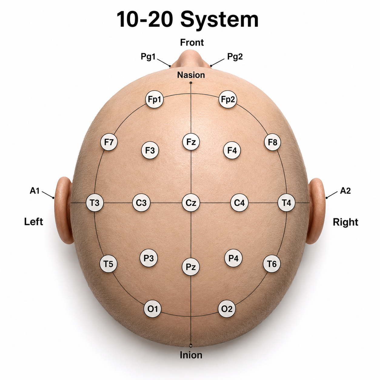
The vertex (Cz) intersects imaginary lines drawn from the nasion to inion and between the two preauricular points. Cz is 50% of the total distance between the nasion and inion and 50% between the two preauricular points.
We adapted this diagram from Fisch (1999).
The 10-20 system received its name because electrode sites are separated by 10% or 20% of the distance between two corresponding anatomical landmarks. In the graphic below, each midline site is 10% or 20% of the distance from the nasion to the inion.
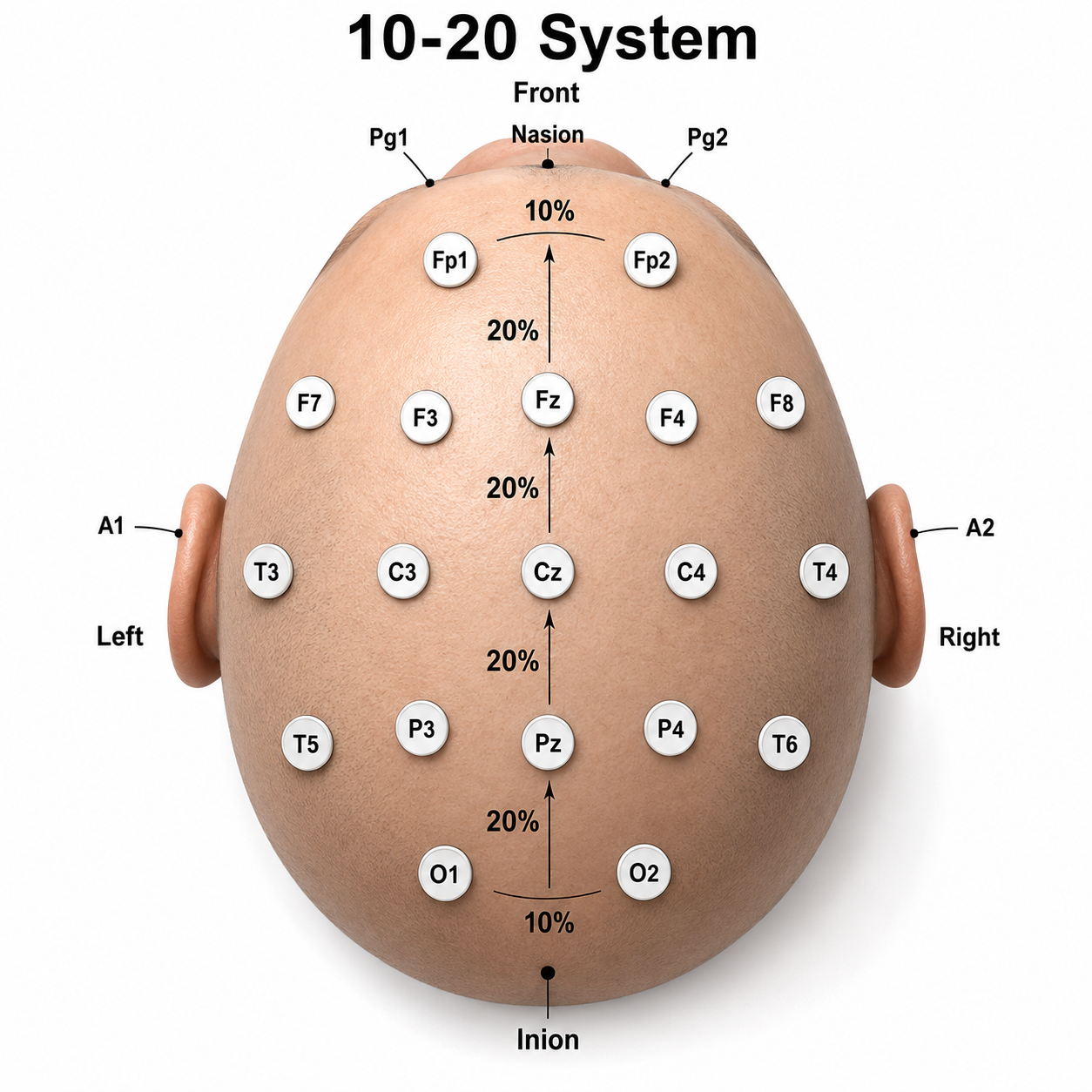
We adapted this graphic from Fisch (1999).
Each horizontal axis site is 10% or 20% of the distance from the two preauricular points.
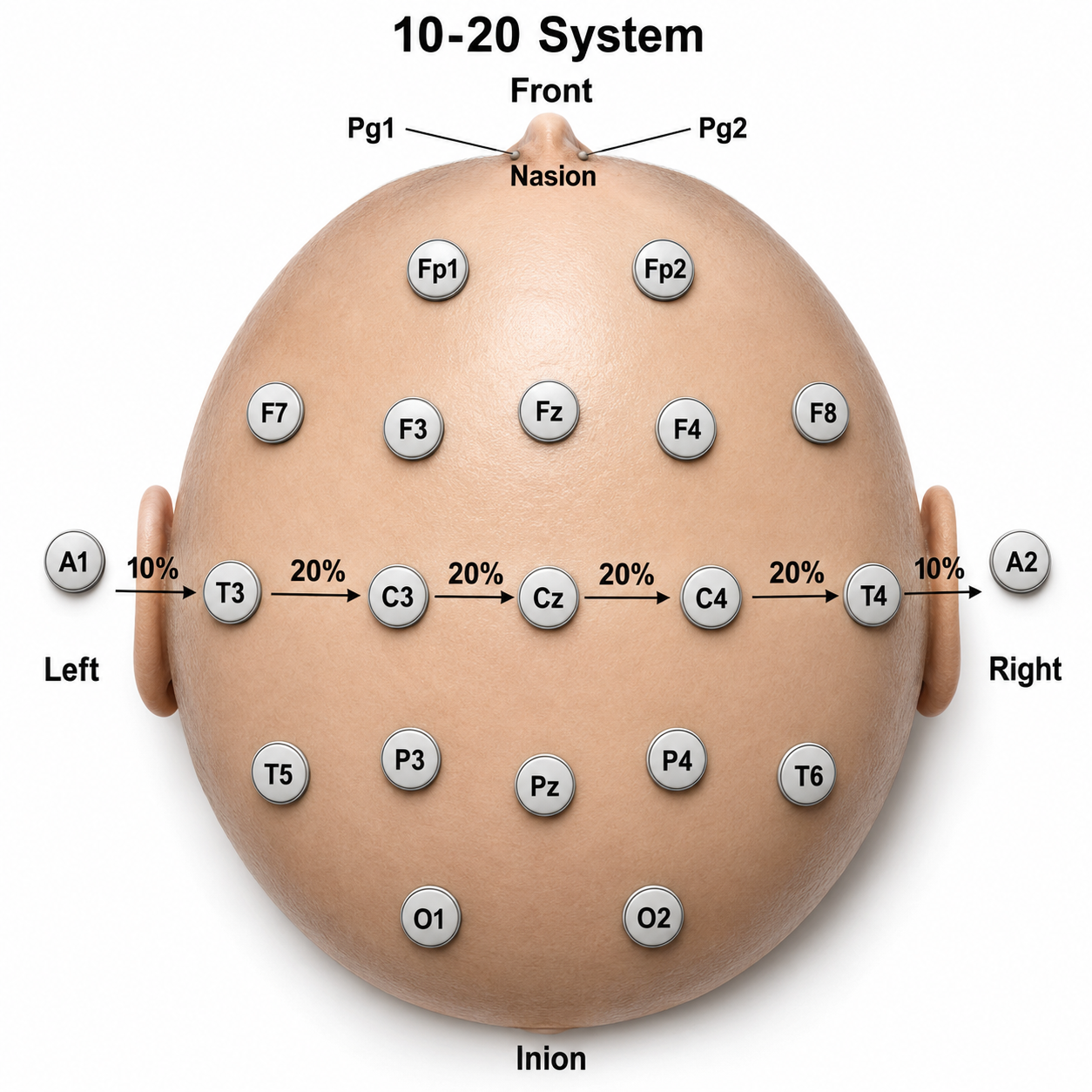
We adapted this graphic adapted from Fisch (1999).
Each circumferential site is 10% of the total circumference, excluding Fpz or Oz.
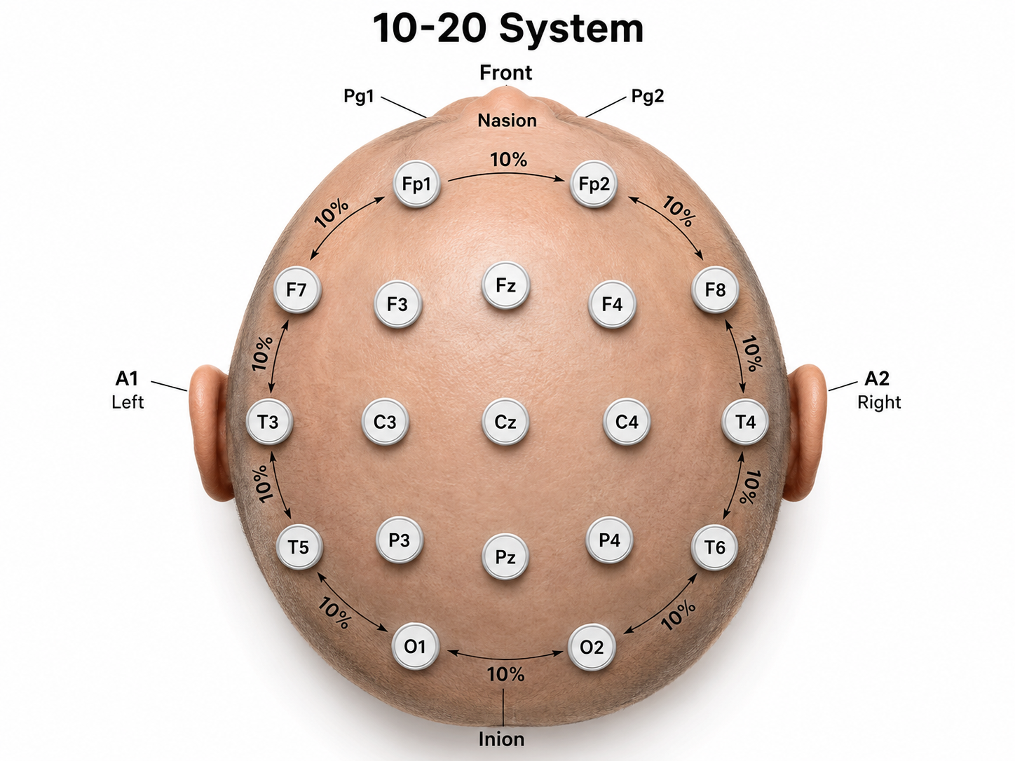
We adapted this graphic from Fisch (1999).
Intermediate sites are halfway between sets of adjacent sites.
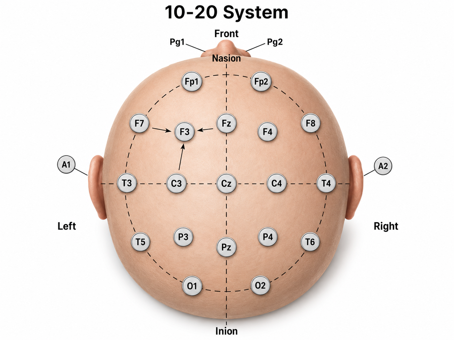
Graphic adapted from Fisch (1999).
The graphic below shows the correspondence between 10-20 sites and Brodmann areas.
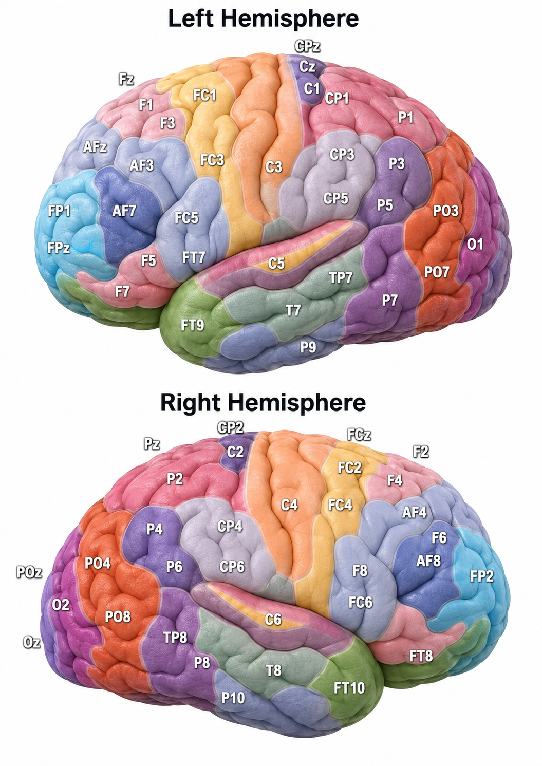
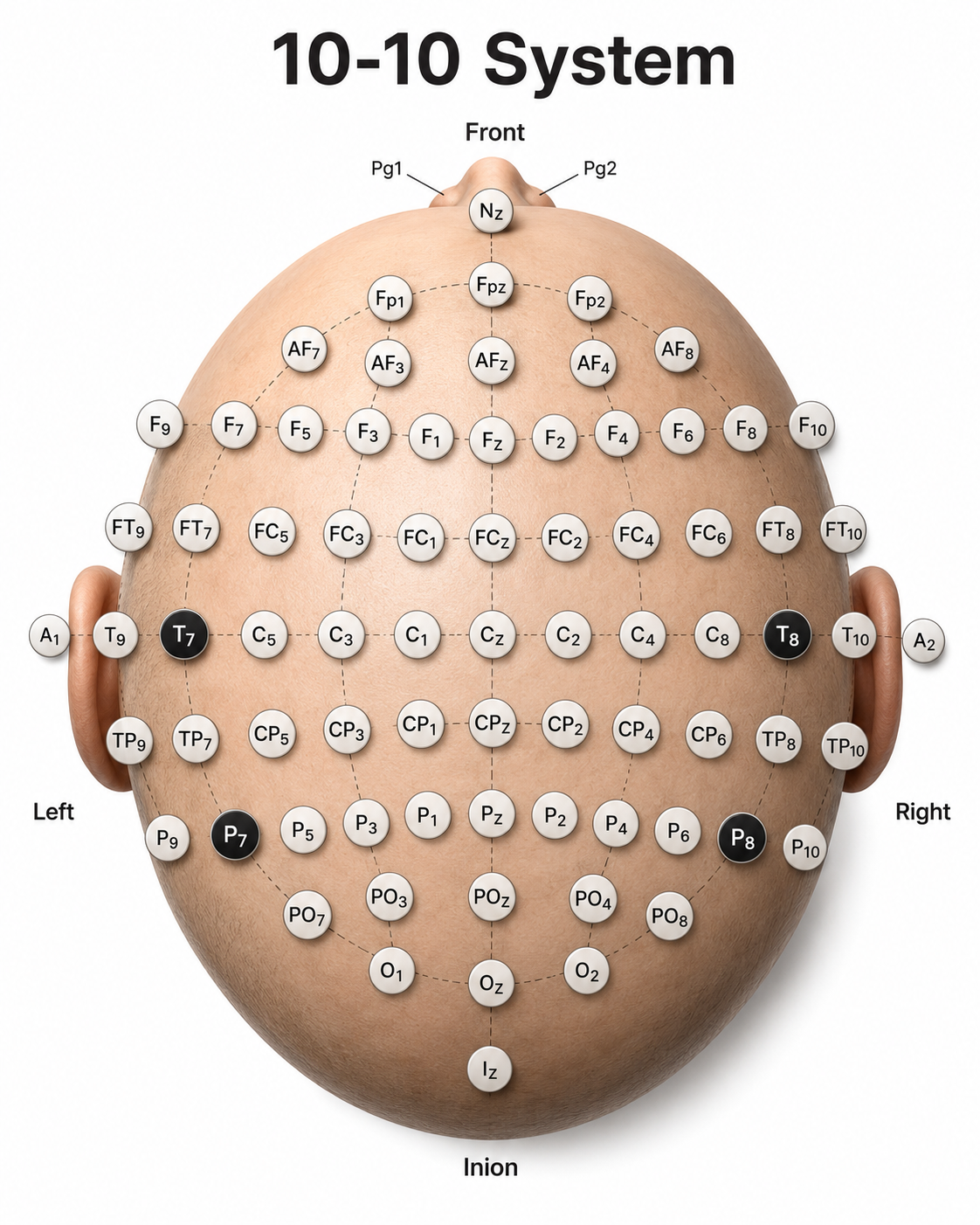
The 10-20 system assigns recording electrodes a letter and subscript. The letters represent the underlying region and include Fp (frontopolar or prefrontal), F (frontal), C (central), P (parietal), O (occipital), and A (auricular). A subscript of z represents a midline (central axis from nasion to inion) placement.
Numerical subscripts range from 1-8 and increase with distance from the midline. The 10-20 system assigns odd-numbered recording electrodes on the left and even-numbered electrodes on the right side of the head. Two reference electrodes are usually placed on the earlobe.
As EEG technology advanced, clinicians extended the classic system into the denser 10-10 array, known as the Modified Combinatorial Nomenclature. This update renames four temporal sites so their labels match their true positions: T3 and T4 became T7 and T8, and T5 and T6 became P7 and P8 (Acharya et al., 2016). You will still meet the older labels in many clinics, so it helps to recognize both. The Signal Acquisition unit describes the 10-10 system in more detail.
We adapted this diagram from Fisch (1999).
Key Concepts
The International 10-20 system is the shared language of electrode placement. Every site is located by measuring set percentages, either 10% or 20%, of the distance between fixed anatomical landmarks: the nasion, the inion, and the two preauricular points. Because the same landmarks and proportions are used for every client, a site such as Cz refers to the same functional location on any head, large or small. This standardization is what lets clinicians compare recordings across sessions, clients, and normative databases.
Key Takeaways
Competence in EEG setup spans measuring the scalp, locating and preparing 10-20 sites, attaching electrodes or a cap, applying conductive gel, and making correct hardware and amplifier connections. It also includes checking impedance, running tracking and continuity tests, detecting and removing artifact, obtaining eyes-open and eyes-closed data, and troubleshooting equipment. The International 10-20 system locates 19 active sites plus reference and ground by taking 10% or 20% of the distance between the nasion, inion, and preauricular points. Electrode labels encode region and side, with letters for frontopolar, frontal, central, parietal, occipital, and auricular areas, odd numbers on the left and even numbers on the right, and z for midline. Understanding these conventions lets you place sensors accurately and interpret assessment reports.
Check Your Understanding
- Which four anatomical landmarks anchor the International 10-20 system, and how are they used?
- How does the 10-20 system get its name?
- What do the letters and numerical subscripts in an electrode label such as F3 or P4 tell you?
- Why are checking impedance and detecting artifact part of basic EEG competence?
- How is Cz located, and why is it a useful starting point for other placements?
10-20 System Electrode Placements
Short Cuts for Electrode Placement
Most sites do not require all the steps outlined below. Calculate Cz by marking 50% of the nasion-inion distance and 50% of the left-right preauricular distance. You can obtain Fz, Pz, C3, C4, T3, and T4 from these two measurements. The Biofeedback Foundation of Europe generously provided the site location, preparation instructions, and graphics.
Step-By-Step Guide for Electrode Placement
Consistently mark perpendicularly on the same side of the measuring tape.
Nasion to Inion – Anterior to Posterior
- Measure from nasion to inion. Note the total and keep the tape measure on this line.
- Mark 50% (or halfway). This is Cz.
- Mark 20% forward from Cz. This is Fz.
- Mark 20% forward from Fz. This is FPz. This should be 10% up from the nasion.
- Mark 20% back from Cz. This is Pz.
- Mark 20% back from Pz. This is Oz. This should be 10% up from the inion.
Ear to Ear (Pre-Auricular)
- Measure from pre-auricular notch to pre-auricular notch. Find the tragus (the flap at the opening of the ear). Move forward to the indention between the skull and jaw. Place the end of the tape measure at this notch and pass it over Cz and to the pre-auricular notch on the opposite ear. Record this measurement.
- Mark 50% (or halfway). This should intersect with Cz and form a “+.”
- From Cz, mark 20% on each side toward the tragus. These will be C3 and C4.
- From C3 and C4, mark 20% toward the tragus. These will be T3 and T4. These sites will be 10 percent up from the pre-auricular notch, directly above the ear.
Circumferential Measurements
- Place the tape measure on FPz, T3, Oz, T4, and back to FPz. Record the total circumference.
- From FPz, mark 5% on either side. These will be FP1 and FP2.
- From Oz, mark 5% on either side. These will be O1 and O2.
- Mark at 10% increments from FP1 and FP2. These will be F7 and F8.
- Mark at 10% increments from O1 and O2. These will be T5 and T6.
Final Measurements
- Measure from Fz to F7: 50% between these points is F3.
- Measure from Fz to F8: 50% between these points is F4.
- Measure from Pz to T5: 50% between these points is P3.
- Measure from Pz to T6: 50% between these points is P4.
Key Takeaways
The 10-20 system is measured, not eyeballed. Find your four anchors first, the nasion, inion, and the two preauricular points, then work outward in set percentages from those landmarks. Confirm Cz from both the front-to-back and the side-to-side measurements, because if the two marks do not meet, the whole grid drifts. Mark consistently on the same side of the tape so small errors do not accumulate. Estimating positions rather than measuring them is discouraged; the American Clinical Neurophysiology Society notes that a placement is only truly 10-20 when head measurements have actually been made (Sinha et al., 2016).
Check Your Understanding
- Which four anatomical landmarks do you locate before any other site, and why?
- How do you find Cz, and why must you confirm it from two measurements?
- Why should you always mark on the same side of the measuring tape?
- What is the difference between a measured 10-20 placement and an estimated one?
- Starting from Cz, which nearby sites can you derive from your first two measurements?
Choosing Your Electrodes: Separate Sensors or a Full Cap
Before you prepare a single site, decide how you will record, because two setups dominate neurofeedback practice. You can attach three separate electrodes for a focused, single-channel recording, or you can fit a full cap that holds nineteen or more electrodes for a whole-head qEEG. The choice should follow your goal rather than your convenience.
Every basic recording uses three electrodes, each with a distinct job. The active electrode sits over the site of interest, such as O1 for occipital alpha or Cz for a vertex protocol. The reference electrode, usually on an earlobe or mastoid, is the comparison point for the measurement. The ground electrode, sometimes called the bias electrode, gives the amplifier's input stage a common voltage reference and stabilizes the connection between client and equipment (Collura, 2014). The cancelling of shared noise is done by the differential amplifier itself, through common-mode rejection; the ground makes that rejection possible rather than performing it.
Key Concepts
The EEG trace is not the voltage at a single electrode. It is the voltage difference between the active electrode and the reference, stabilized by the ground. This one idea explains a great deal of what you will see. It is why moving the reference changes the waveform, why a poor ground can contaminate every channel at once, and why a single failing electrode can distort what looks like brain activity. Keep it in mind whenever a recording surprises you.
Three separate electrodes are ideal for teaching, for single-site training, and for demonstrating artifacts, because they are quick to place and easy to inspect. A full cap is the right tool when you need a montage of many sites at once, as in qEEG assessment, where nineteen scalp electrodes plus references and ground are recorded together. The American Clinical Neurophysiology Society specifies that “sixteen channels of simultaneous recording are considered the minimum number required to show the areas producing most normal and abnormal EEG patterns,” and separately that all 21 electrode positions of the 10-20 system should be used (Sinha et al., 2016). Channels and electrodes are different quantities, and conflating them understates what a routine clinical EEG requires. More electrodes mean more setup time but a far richer picture of the brain.
Both separate electrodes and caps come in wet and dry versions. A wet electrode uses conductive gel or conductive paste to bridge scalp and sensor, which lowers and steadies impedance but takes longer and leaves a mess.
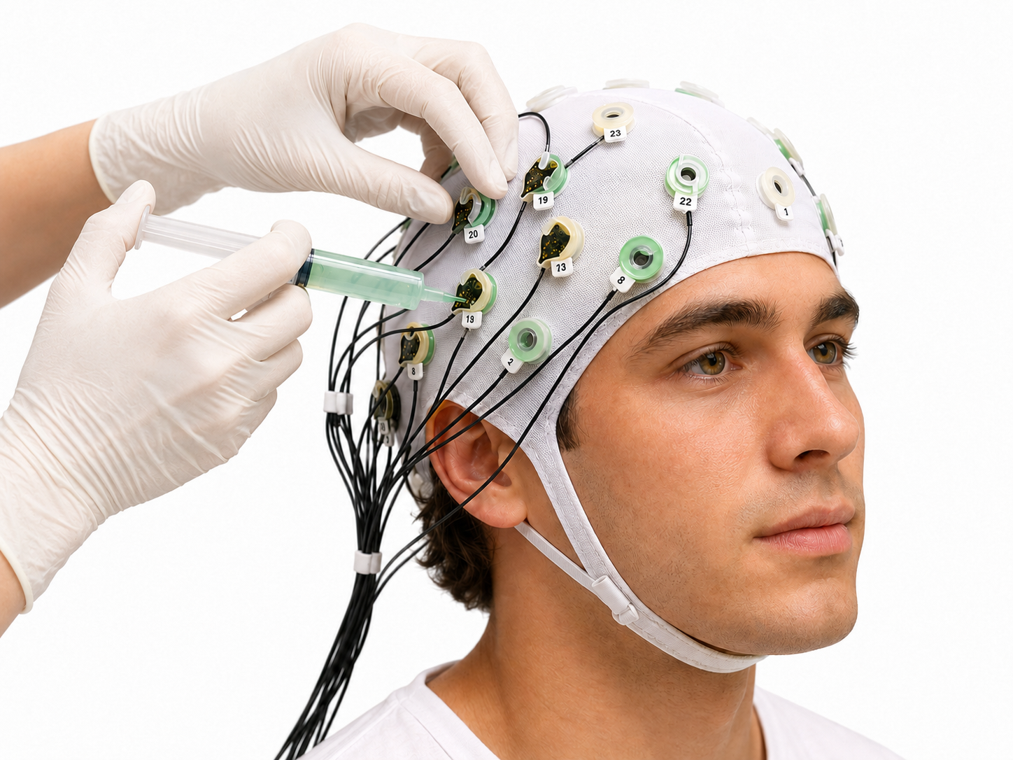
A dry electrode uses pins, combs, or firm pads that press through the hair to touch the scalp, so it skips the gel and speeds up setup, but its impedance runs higher and less stable and comfort becomes the limiting factor.
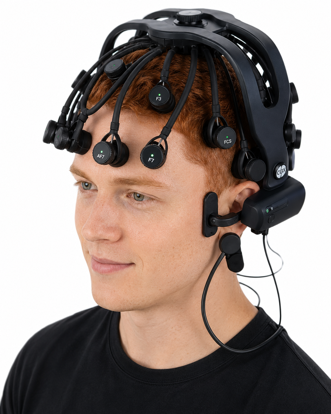
Choose wet for the cleanest signal and research-grade data, and dry for speed and convenience when the task tolerates a noisier trace. Note that needle electrodes are not recommended for routine clinical use, because of patient discomfort, risk of injury to personnel, and higher impedance that raises noise; the guideline makes a narrow exception for subdermal needle or wire electrodes in stuporous or comatose patients when cup electrodes are not feasible (Sinha et al., 2016).
Key Takeaways
Every basic recording uses three electrodes with distinct jobs: an active electrode over the site of interest, a reference for comparison, and a ground or bias electrode for noise control and stability. The EEG you see is the voltage difference between active and reference, not a reading from one point, so both the reference and the ground shape the trace. Use three separate electrodes for focused single-channel work and teaching, and a full cap of nineteen or more electrodes for qEEG and whole-head assessment. Wet electrodes give lower, steadier impedance at the cost of time and mess, while dry electrodes trade some signal quality for speed and convenience. Match the setup to your clinical goal, not to whichever is fastest.
Check Your Understanding
- What are the three electrode roles in a basic recording, and what does each one do?
- Why is it accurate to call the EEG a voltage difference rather than a reading from a single electrode?
- When would you choose three separate electrodes over a full cap, and when the cap?
- How do wet and dry electrodes differ in preparation, impedance, and signal quality?
- Where are reference and ground electrodes usually placed, and why those sites?
Site Preparation
Infection control is now part of site preparation, and the level of protection should follow a risk assessment rather than a fixed routine. For routine training on intact skin, hand hygiene before and after client contact is the essential measure; gloves are indicated when you anticipate contact with non-intact skin, bodily fluids, or contaminated equipment, such as handling used sensors or abraded sites. Masks and eye protection are indicated when you work within two metres of a client with respiratory symptoms or when splashes are possible, and disposable masks should be available for clients who want them. Applying gloves, a mask, and a face shield to every contact regardless of risk is not what current guidance recommends, and indiscriminate glove use has itself been linked to pathogen transmission. See the unit on Aseptic Techniques for a more comprehensive review of infection mitigation.
The steps below prepare a site for a wet cup electrode filled with conductive paste, the setup you will use most often for single-channel and three-electrode recordings. Dry separate electrodes follow at the end of this section, and full caps have their own section.
Once a site is identified and marked, site preparation and sensor placement when using individual sensors follow these steps:
- Instruct clients to wash their hair and not use any conditioner or hair-styling products. A recent haircut is helpful (particularly for children), and hair must be brushed or combed.
- Prepare the scalp by cleaning with alcohol. Let the alcohol dry before applying the electrodes.
- The following is a typical recommendation when using older amplifiers. Modern amplifiers with high input impedance do not require this step. Additionally, the following step is controversial because the old standard of achieving skin-electrode impedance below 5 Kohms has been challenged as unnecessary and risks infection transmission (Ferree et al., 2001; Kappenman & Luck, 2010). The authors of this work do not recommend this step, especially during the COVID-19 pandemic. Still, we included it because it remains an accepted standard in the field of electroencephalography: slightly abrade the skin with a blunted needle that you must discard after use to remove dead skin, dirt, and oil that can weaken the EEG signal.
- Ask your client to remove jewelry. If your client has pierced ears, do not place the electrode over the hole.
- Scoop up a small quantity of NuPrep™ skin preparation gel or a similar product on a cotton swab or tissue.
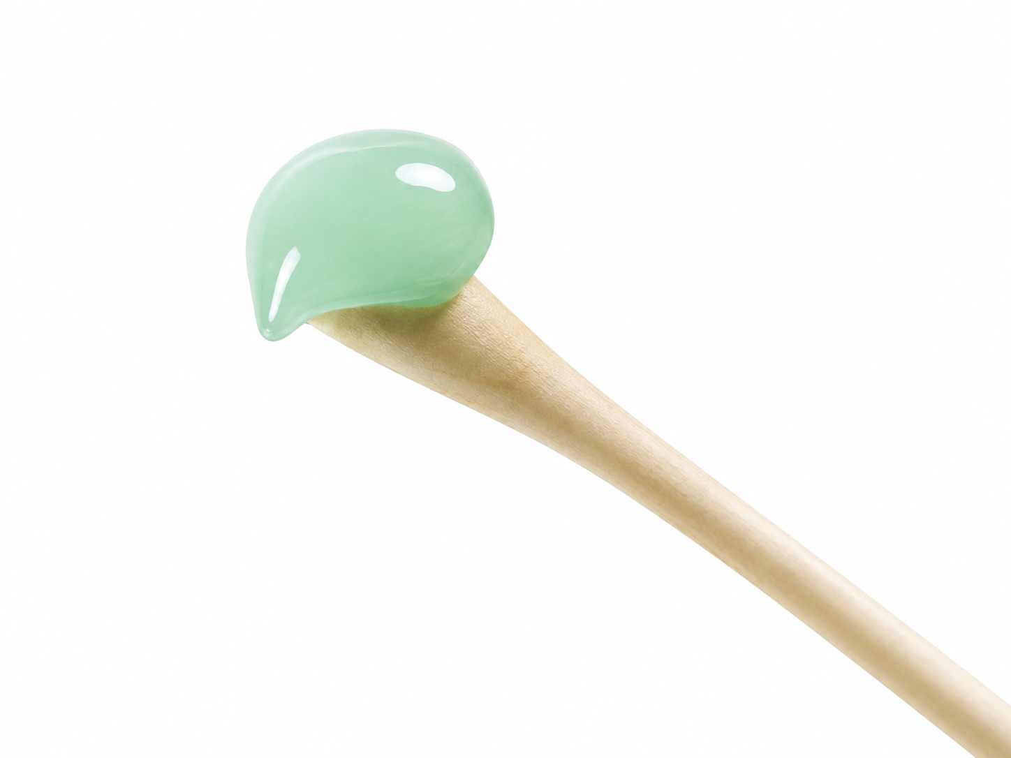
- Be careful to avoid contaminating the gel tube by avoiding direct contact with the Q-tips®.

- With the thumb and index finger of one hand, separate the hair around the electrode site that was previously found and marked.
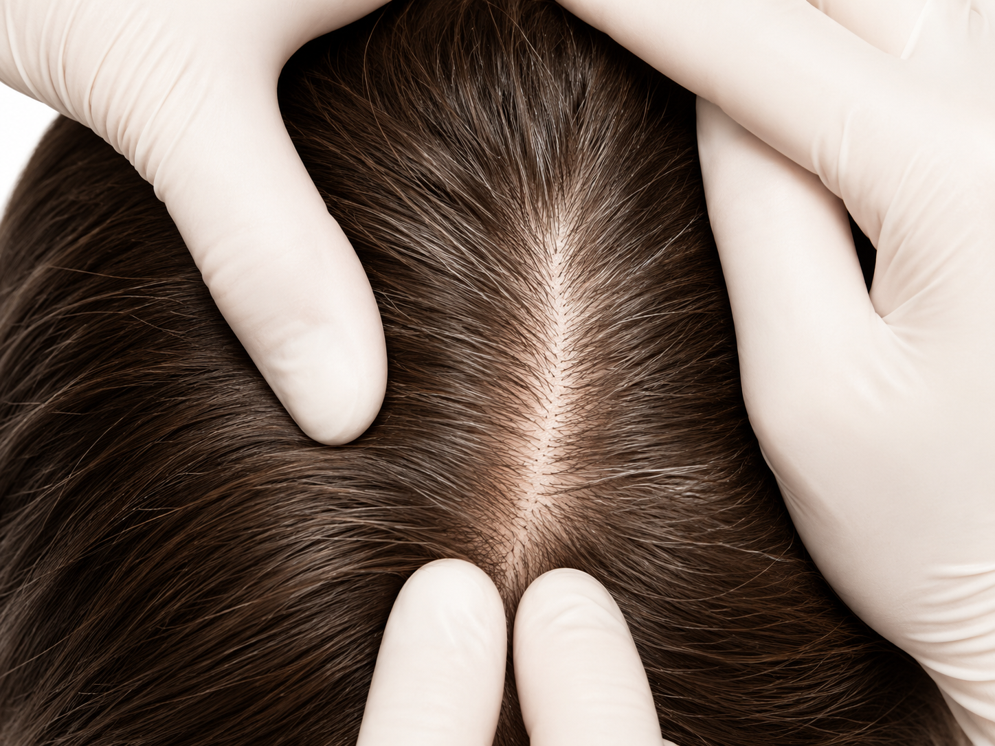
- Run the gel in the direction of the natural line formed along the scalp by the split hair. Some light force must be used, enough to redden the scalp slightly (again, not recommended but an accepted standard), but not enough to break the skin.
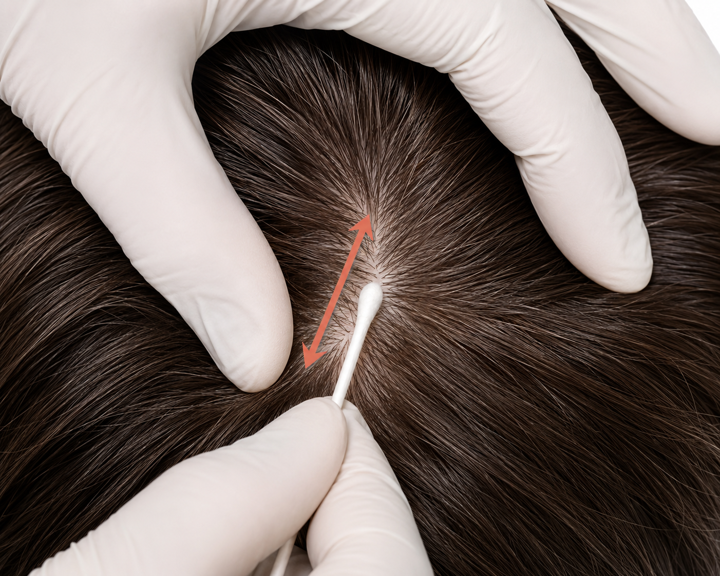
- Wipe away the excess prepping gel with a dry, lint-free cloth. Take care to keep the hair parted and keep track of the site after wiping clean.
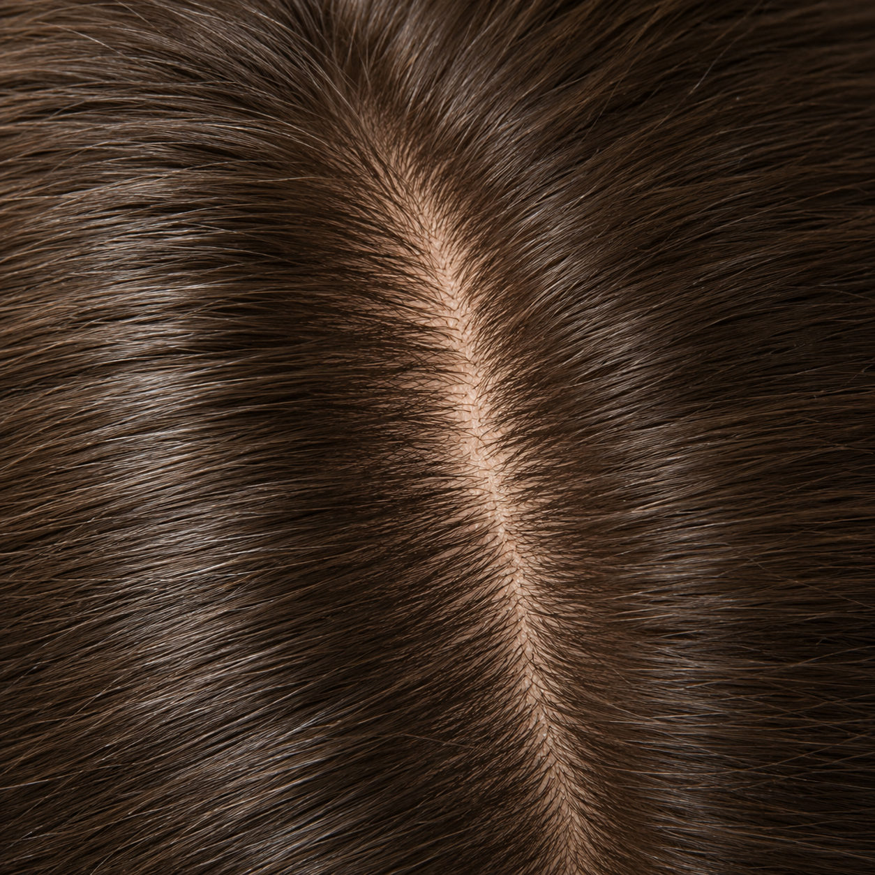
- Use a popsicle or craft stick to cover the electrode with a 1/4-inch layer of Ten20™ conductive paste. Gently press the electrode onto the skin surface until the paste flattens out under the electrode.

- Secure the electrode cables to the client and ensure strain relief.
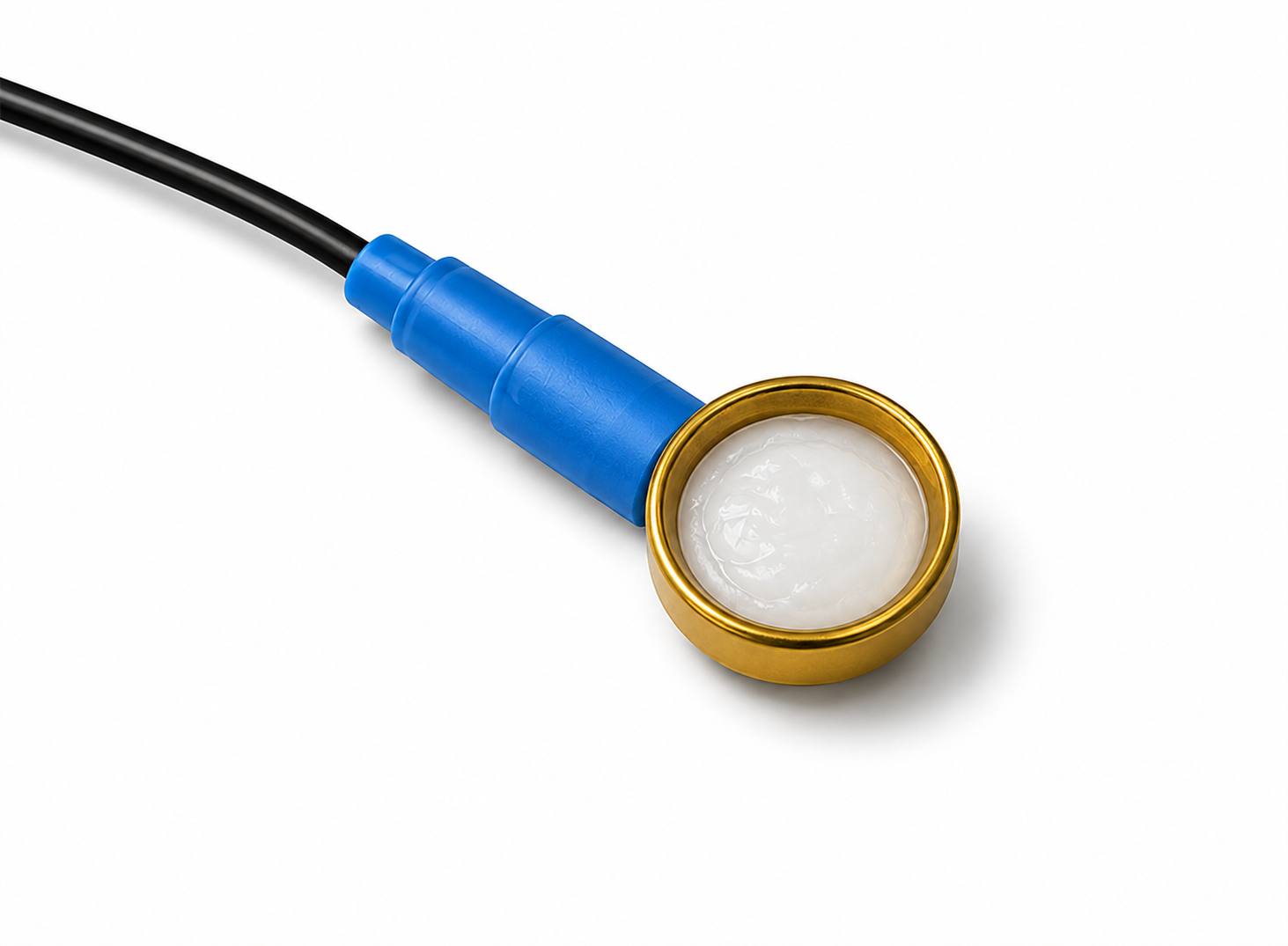
- Fill the electrode cup with Ten20™ conductive paste so that no air bubbles exist in the cup.
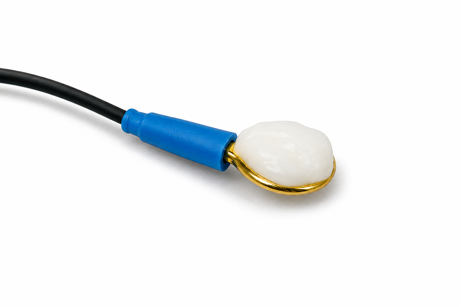
- Add more Ten20™ conductive paste onto the cup electrode, just enough to form a ball on the cup, not so much that it spills over the edge. The ideal amount of paste is shown.
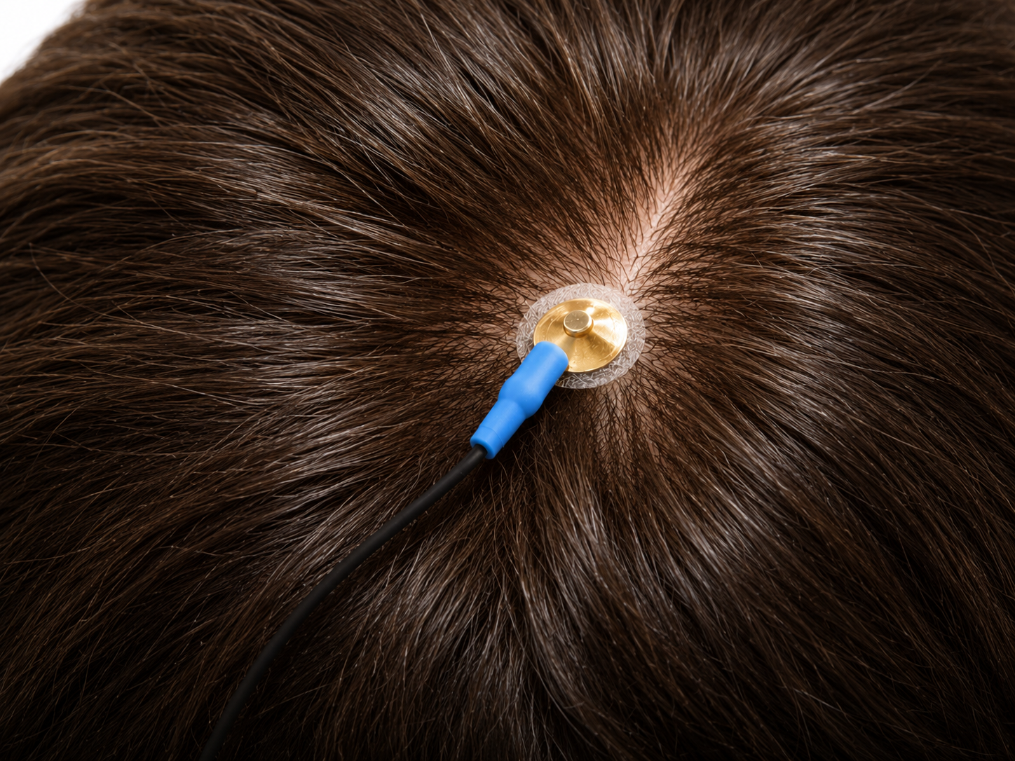
- Place the cup face down on the landing pad previously prepared. Gently push the electrode down to fix it to the scalp. A little bit of paste should run out along the edge of the cup to form a thin ring around it. Place the electrode so that the direction of the cable does not place undue stress on the cup, so that it does not get pulled, lifted, or twisted off. The cable should hang naturally and towards the plastic clip, and enough slack should be left to allow for comfortable head movement.
- Repeat the above preparation and placement steps on the earlobes. Do not put too much paste on the ear clip electrode, but ensure that the gold disc is completely covered.
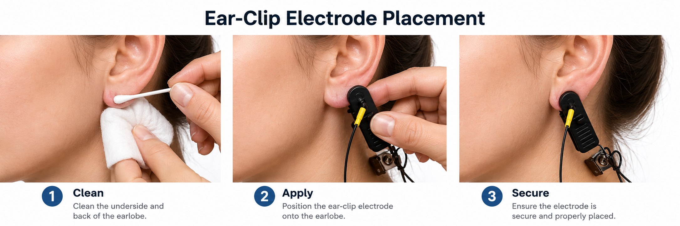
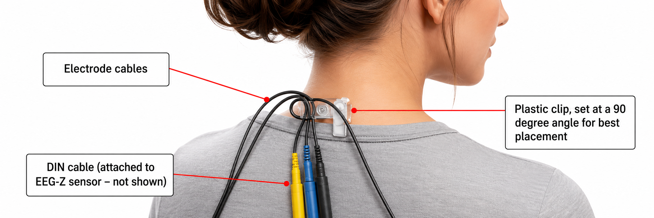
- Leave enough slack in the cable to allow the patient to turn their head easily, but not too much that it can get caught. Think about the angle of the cable from the ear clip to the neck clip so that no extra tension is placed on the ear clip. Note the position of the clip, the direction of the cables, and the slack left to provide mobility. The final configuration should look like the photograph below when viewed from behind.
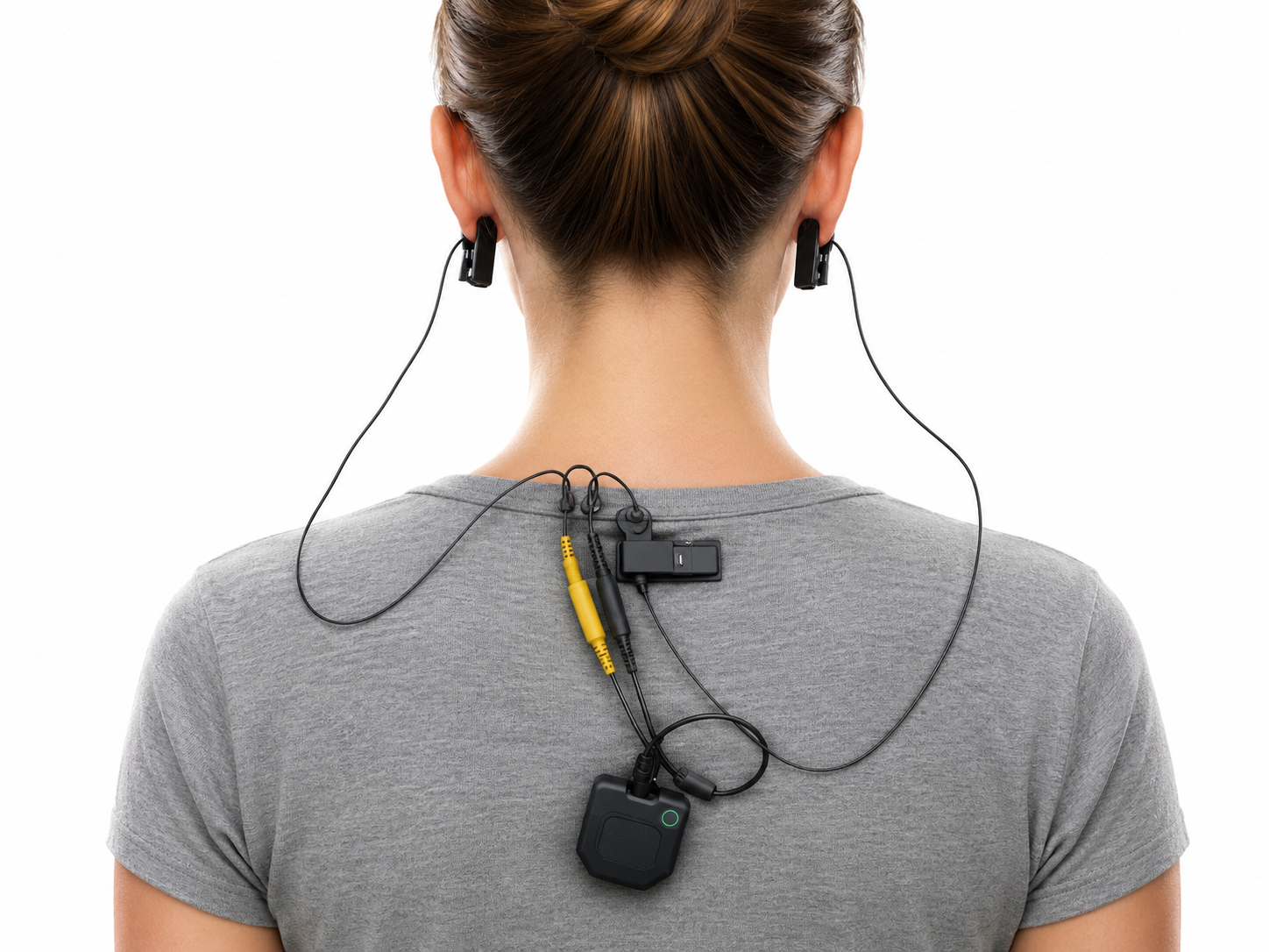
Use enough paste to complete the path from scalp to sensor, but no more. Excess paste that spreads from one electrode to the next forms a salt bridge, an unintended conductive path that merges two channels into one and makes their data useless. This is the same mechanism behind the bridging artifact, so wipe away any excess before it reaches a neighboring site (Sinha et al., 2016).
This movie is a 19-channel BioTrace+ /NeXus-32 display of EEG recording © John S. Anderson.
Applying Three Dry Electrodes
Dry electrodes skip the gel, so the setup is faster but the mechanics matter more. With no electrolyte to steady the interface, a dry electrode depends on direct contact and gentle mechanical pressure, which means hair, motion, and fit have a larger effect on the signal. Prepare three dry electrodes as follows.
- Confirm the client's hair is dry and free of styling product.
- Choose the sensor shape for each site: a flat pad for the forehead, earlobe, or mastoid, and a pin or comb sensor for hair-covered scalp.
- Tell the client to expect gentle pressure, never sharp pain.
- Place the active dry electrode at the marked site, parting the hair so the contact points reach skin rather than resting on hair.
- Place the reference and ground electrodes on the earlobe, mastoid, or forehead.
- Secure the sensors with a headband, elastic wrap, adhesive holder, or spring frame.
- Increase pressure gradually until the trace is stable and the client stays comfortable, and reposition at once if there is pinching, headache, or lingering discomfort.
Do not hold a dry electrode to the impedance target you use for wet electrodes. Dry contacts read much higher and less stable impedances because no electrolyte stabilizes the interface, so judge them by the manufacturer's contact-quality scale and the live trace rather than a wet-electrode pass or fail number.
Key Takeaways
Site preparation begins with a clean, product-free scalp and, in the era of COVID-19, appropriate masks, a face shield, and gloves for the clinician. For a wet electrode, part the hair, apply a small amount of preparation gel along the part, wipe away the excess, and seat a paste-filled cup so a thin ring of paste forms around it without spreading to a neighbor. For a dry electrode, skip the gel and rely on gentle mechanical pressure, adjusting contact until the trace is stable and the client stays comfortable. Route each cable with strain relief and enough slack for comfortable head movement, and repeat the process on the earlobe references. Modern high-input-impedance amplifiers make aggressive skin abrasion unnecessary, so it is now discouraged for both comfort and infection control.
Check Your Understanding
- What infection-control measures does current practice recommend during site preparation?
- What are the key steps in preparing a site and seating a wet cup electrode with conductive paste?
- How does preparing three dry electrodes differ from preparing wet electrodes?
- Why should you leave slack in the electrode cable and provide strain relief?
- How does earlobe reference preparation differ from scalp site preparation?
Applying a Full Electrode Cap
When you need many sites at once, a full electrode cap replaces dozens of separate placements with a single fitted garment. A well-fitted cap holds each electrode close to its 10-20 target, so sizing is not a step to rush. An ill-fitting cap shifts electrodes away from the regions they are meant to record and quietly undermines every site.
Fitting a Wet Cap
- Measure head circumference with a flexible tape around the widest part of the head, passing just above the eyebrows and over the inion.
- Match the measurement to the manufacturer's sizing chart, and when a client falls between sizes, choose the snugger cap if it stays comfortable.
- Have the client hold the front edge against the forehead while you stretch the cap back over the head.
- Align Cz at the intersection of the nasion-to-inion and preauricular-to-preauricular midpoints, exactly as you would for a single vertex placement.
- Check symmetry so that Fp1 and Fp2 are level and equidistant from the midline, and secure any chin strap snugly without restricting the jaw or airway.
With the cap seated, prepare each site through its electrode well. Part the hair with a blunt applicator until the scalp shows, then fill the well with conductive gel so a solid column connects scalp to sensor with no air gap. Fill just enough to make contact. Overfilling lets gel spread from one well to the next and form a salt bridge that merges neighboring channels, the same problem you guard against with separate electrodes.
Fitting a Dry Cap
A dry cap carries the same 10-20 logic but no gel. Its electrodes reach the scalp through pins or spring-loaded contacts that part the hair under gentle tension, so fit and pressure do the work that gel does in a wet system. Size and seat the cap the same way, aligning Cz and checking symmetry, then adjust the tension until the trace is stable and the client stays comfortable. Expect higher and less stable impedances than a wet cap, and judge contact by the system's own quality scale rather than a wet-electrode target.
Checking Impedance and Signal Quality
Whatever electrodes you use, check impedance before you record. For clinical EEG, aim for balanced impedances; modern digital amplifiers accept values up to about 10 Kohms when they are balanced, although values below 100 ohms usually signal a short or a salt bridge and should be corrected (Sinha et al., 2016). Neurofeedback practice is more lenient, accepting values under 20 Kohms for general clinical sessions while reserving the stricter targets for research (Demos, 2019). Balance matters more than any single number, because unbalanced impedances weaken the amplifier's ability to reject shared noise.
Impedance tells you the connection is sound; the live trace tells you the recording is usable. Seat the client comfortably, ask them to relax the jaw, and watch the raw signal while you confirm the setup works. With an occipital site, alpha should rise when the eyes close and fall when they open, a blink should produce a large slow frontal deflection, a jaw clench should add fast muscle activity, and touching a cable should produce a movement artifact. Reproducing these on purpose, as you learned earlier, is the fastest way to prove your electrodes are reporting brain activity rather than noise.
Key Takeaways
Cap sizing is not a minor detail: an ill-fitting cap moves every electrode off its target, so measure the head and match the sizing chart before anything else. Seat a cap by aligning Cz at the nasion-inion and preauricular midpoints and checking left-right symmetry, exactly as for a single placement. For wet caps, fill each well with a solid, air-free column of gel, and never overfill, since spreading gel bridges neighboring channels. Dry caps use pressure instead of gel and read higher, less stable impedances, so judge them by the system's contact scale rather than the wet-electrode target. Always confirm that impedances are balanced and above 100 ohms before recording, then watch the live trace respond to eyes open and closed, blinks, and jaw clenches.
Check Your Understanding
- Why does cap size affect the validity of every electrode's recording?
- How do you align and check a cap once it is on the head?
- What is a salt bridge, and how do you prevent one when gelling a wet cap?
- How should your impedance expectations differ between a wet cap and a dry cap?
- What should you see in the live trace when the eyes close, when the client blinks, and when the client clenches the jaw?
Elimination of Artifact from EEG Recording
BCIA's Neurofeedback Essential Skills List requires that applicants identify and remove artifact sources appearing in EEG recordings. Review the Signal Acquisition unit to recognize normal EEG patterns and identify and correct noncerebral origin signals like bridging artifacts. Once you understand the mechanics and appearance of common artifacts, Peper et al. (2008) recommend that you intentionally reproduce them to recognize and prevent them.
Brain map validity depends on the integrity of the raw EEG, and the published requirements are more demanding than clinical habit sometimes assumes. The International QEEG Certification Board and the EEG and Clinical Neuroscience Society specify a minimum of 1 minute of artifact-free data for database comparison, ideally 2 to 5 minutes, with no selected segment shorter than 1 second; they assume a raw record of roughly 10 minutes each of eyes-open and eyes-closed recording (International QEEG Certification Board, n.d.; Sinha et al., 2016). Select that clean data separately for each condition rather than pooling the two. Realize that longer recordings risk increased drowsiness artifacts and sleep. Therefore, it is helpful to speak to the client occasionally to help them maintain alertness, and simply saying how much time is left every 1-2 minutes is usually enough to accomplish this.
Stage 1 sleep is a subtle drowsy state that clients often do not recognize. This state change is seen as a decrease in alpha and an increase in theta amplitudes. There will be slow eye-rolling movements and decreased EMG and beta. Note the increased theta amplitudes in the spectral displays for channels 1 and 2.
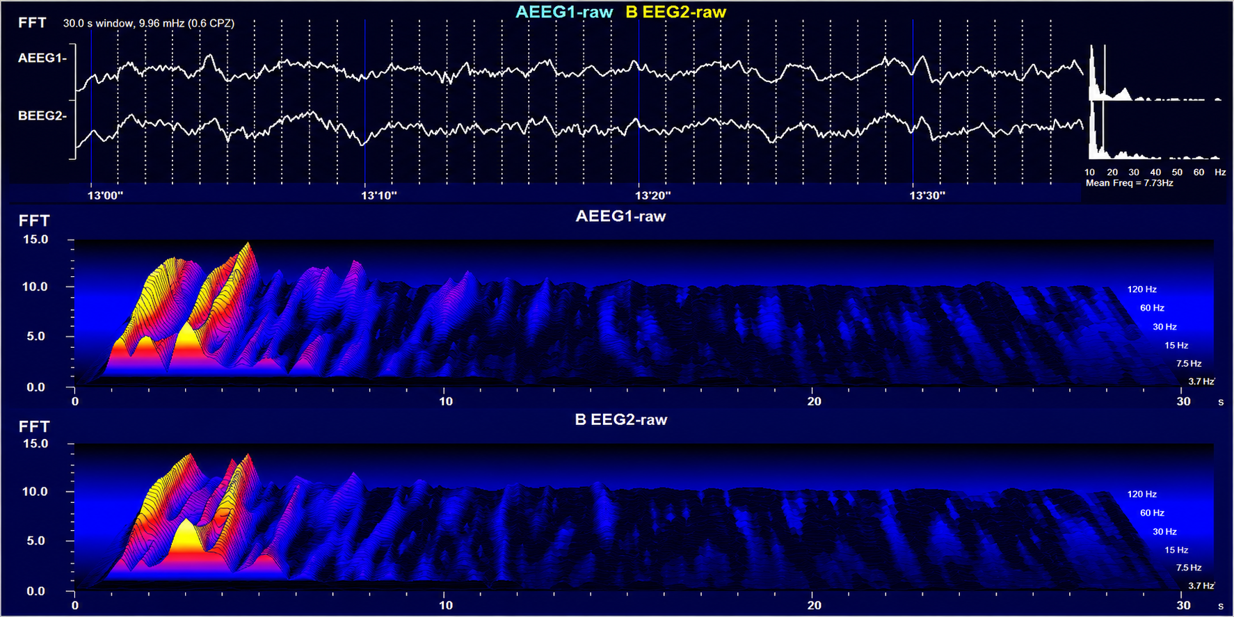
Stage 1 sleep graphic © John S. Anderson. A two-channel display: raw EEG from AEEG1 and BEEG2 across a 30-second window, above waterfall spectrograms for each channel whose logarithmic frequency axis runs from about 3.7 Hz to 120 Hz. The high-power peaks cluster at the low end of that axis and the two channels track each other closely, showing the rise in theta amplitude that marks the drift into Stage 1 sleep. The reported mean frequency of 7.73 Hz sits at the theta-alpha boundary; read the peaks rather than the mean, because it is the shift of power down into theta, not a burst of alpha, that identifies this state.
The less frequent the artifact, the shorter the required recording period. Disable low-pass and high-pass filters before editing to better visualize electro-ocular and SEMG artifacts.
Worst case, as with a hyperactive child, none of the EEG channels may contain usable data, and you will need to repeat the assessment. Where artifact only contaminates a few channels, you may base assessment on the clean channels (Demos, 2019).
Strategies to Reduce Artifact
Demos (2019) recommends several precautions to reduce artifact in raw EEG recordings. Demonstrate how to create artifacts for your clients using screen displays while they clench their teeth, move their eyes, blink, swallow, and fidget. Confirm the cap fits properly, and use reclining chairs with negligible neck cushioning that can force the head downward to minimize SEMG artifact. Limit eyelid movement with cotton balls gently touching the closed eyelids, secured by a loose sleep mask, flexible band, or tape in the eyes-closed recording, ensuring there is no pressure against the eyes.
Ensure that impedance values or DC offset values are appropriate for your amplifier, since values under 5 Kohms are expected for publishable research, while values of less than 20 Kohms are acceptable for general clinical sessions and do not require excessive skin abrasion. Only record qEEG data when the raw waveforms appear clean.
Cutting Edge
For decades, clinicians were taught to abrade the skin until skin-electrode impedance fell below 5 Kohms. That standard has been challenged as unnecessary with modern high-input-impedance amplifiers and as a needless infection risk (Ferree et al., 2001; Kappenman & Luck, 2010). Current practice accepts values below 20 Kohms for general clinical sessions without aggressive abrasion, reserving the stricter target for publishable research. This shift, reinforced by pandemic-era infection control, illustrates how an accepted standard can evolve as instrumentation improves.
This movie is a 19-channel BioTrace+ /NeXus-32 display of EEG processing in NeuroGuide™ © John S. Anderson.
EEG Patterns of Concern and Generally Benign Patterns
Abnormal EEG patterns include abnormal slow activity, paroxysmal epileptogenic abnormalities, and abnormal periodic paroxysmal patterns.
Abnormal Slow Activity
Abnormal slow activity includes generalized intermittent slow activity, focal and lateralized intermittent slow activity, and persistent slow activity.
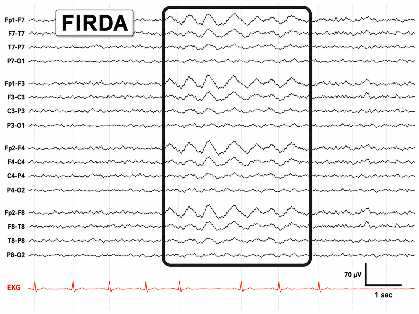
Generalized intermittent slow activity is asynchronous, under 8 Hz, and involves the majority or all of both hemispheres. These bursts typically consist of polymorphic delta (Benbadis & Rielo, 2018). Alerting and opening the eyes reduce, whereas hyperventilation challenge and relaxation increase these slow waves (Fisch, 1999).
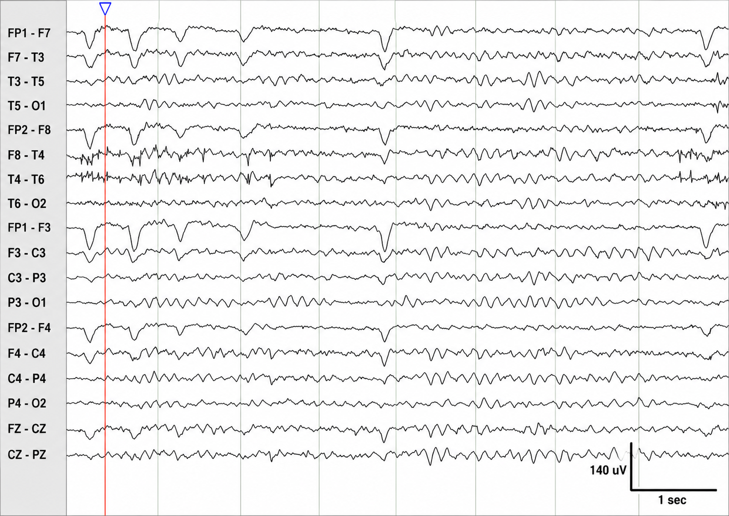
Graphic © Medscape.
Focal and lateralized intermittent slow activity is under 8 Hz and is usually confined to a single or a couple of adjacent electrodes. These bursts have an irregular appearance, are composed of several frequencies, and rarely involve an entire hemisphere (Fisch, 1999).
Graphic © eegatlas-online.com.
Persistent slow activity consists of theta and delta waveforms. Distribution may be anterior or widespread in encephalopathies (Richardson & Benbadis, 2019).
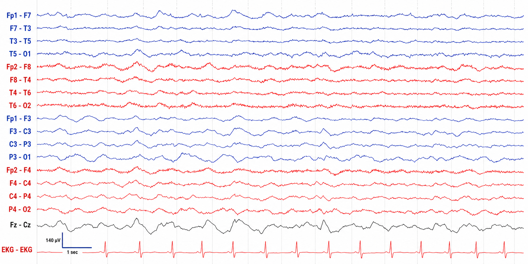
Graphic © Medscape.
Paroxysmal Epileptogenic Abnormalities
Paroxysmal epileptogenic abnormalities include interictal epileptiform discharges (focal, generalized), ictal, secondary bilateral synchrony, and epileptiform patterns of doubtful significance.
Interictal epileptiform discharges typically consist of individual spikes and sharp waves and complexes that contain both waveforms that last less than 2 seconds (Fisch, 1999).
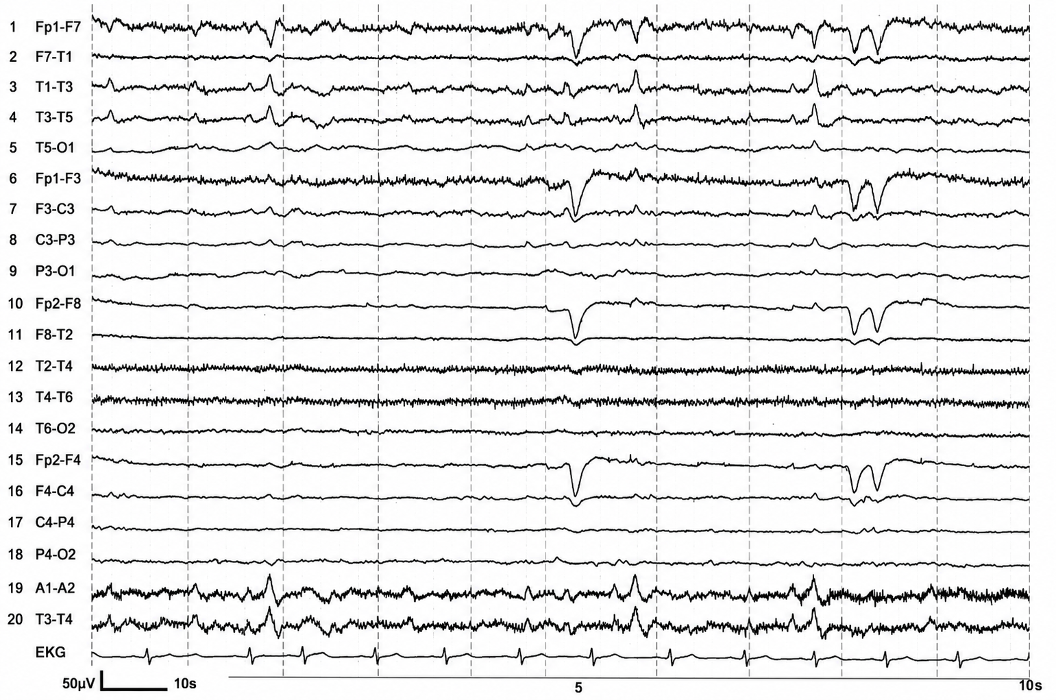
Graphic courtesy of Teppei Matsubara.
Ictal epileptiform discharges may consist of prolonged interictal activity. These may include 3-Hz spike-and-wave discharges, slow spike-and-wave discharges, sharp-and-slow-wave discharges, amplitude and frequency fluctuations in rhythms of 10 Hz or higher, and irregular multiple spike-and-wave or spike-and-wave discharges (Fisch, 1999).
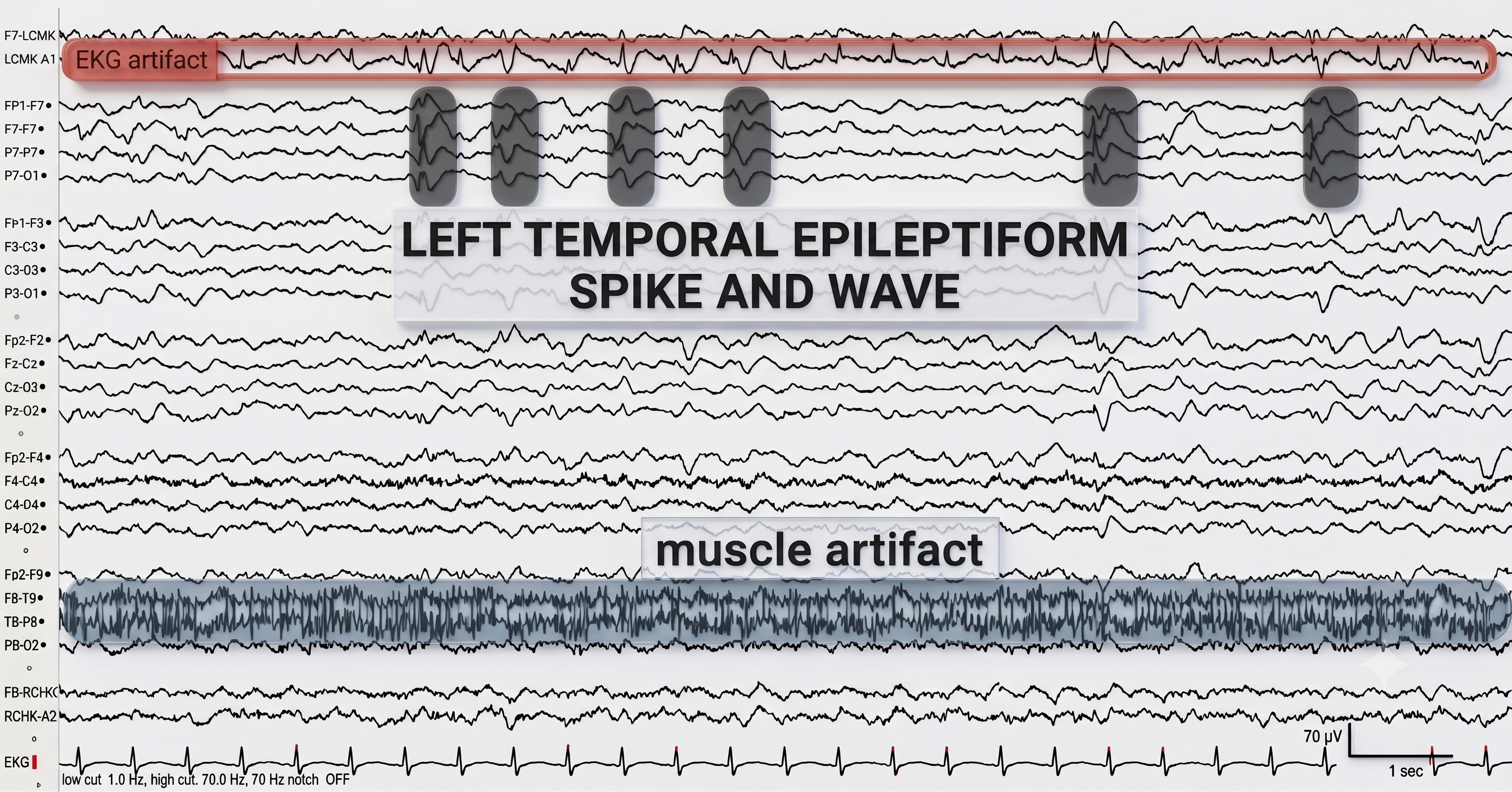
Graphic © eegatlas-online.com.
Secondary bilateral synchrony (SBS) involves spikes with a single phase reversal around the midline (Jin, 2007).
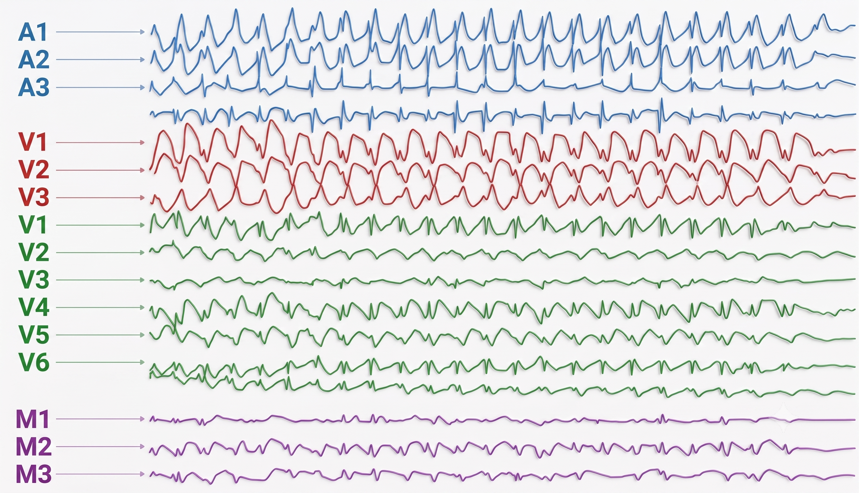
Graphic © Neurology Asia.
Epileptogenic patterns of doubtful significance are brief and not associated with seizures or neurological disorders. Examples are 6-Hz spike-and-slow-wave, 14- and 16-Hz positive bursts, benign epileptiform transients of sleep (BETS), rhythmical mid-temporal discharge (RMTD), small sharp spikes (SSS), and wicket spikes (Fisch, 1999).
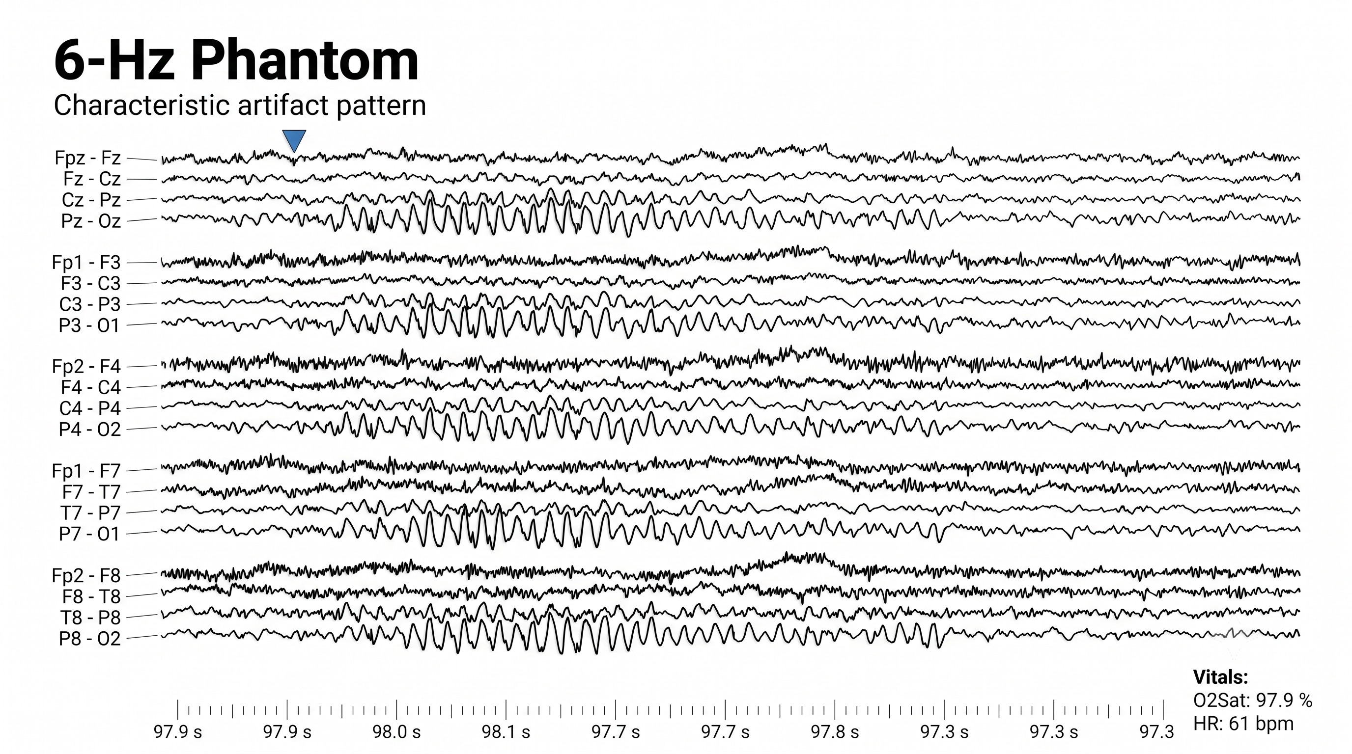
Six-Hz graphic © Mayo Foundation for Medical Education.
Abnormal Periodic Paroxysmal Patterns
Abnormal periodic paroxysmal patterns include generalized periodic paroxysmal patterns and lateralized periodic paroxysmal patterns. Generalized periodic paroxysmal patterns involve the same areas of both hemispheres. The waveforms exhibit similar composition, amplitude, and phase in each hemisphere but may slightly vary within a hemisphere (Fisch, 1999).
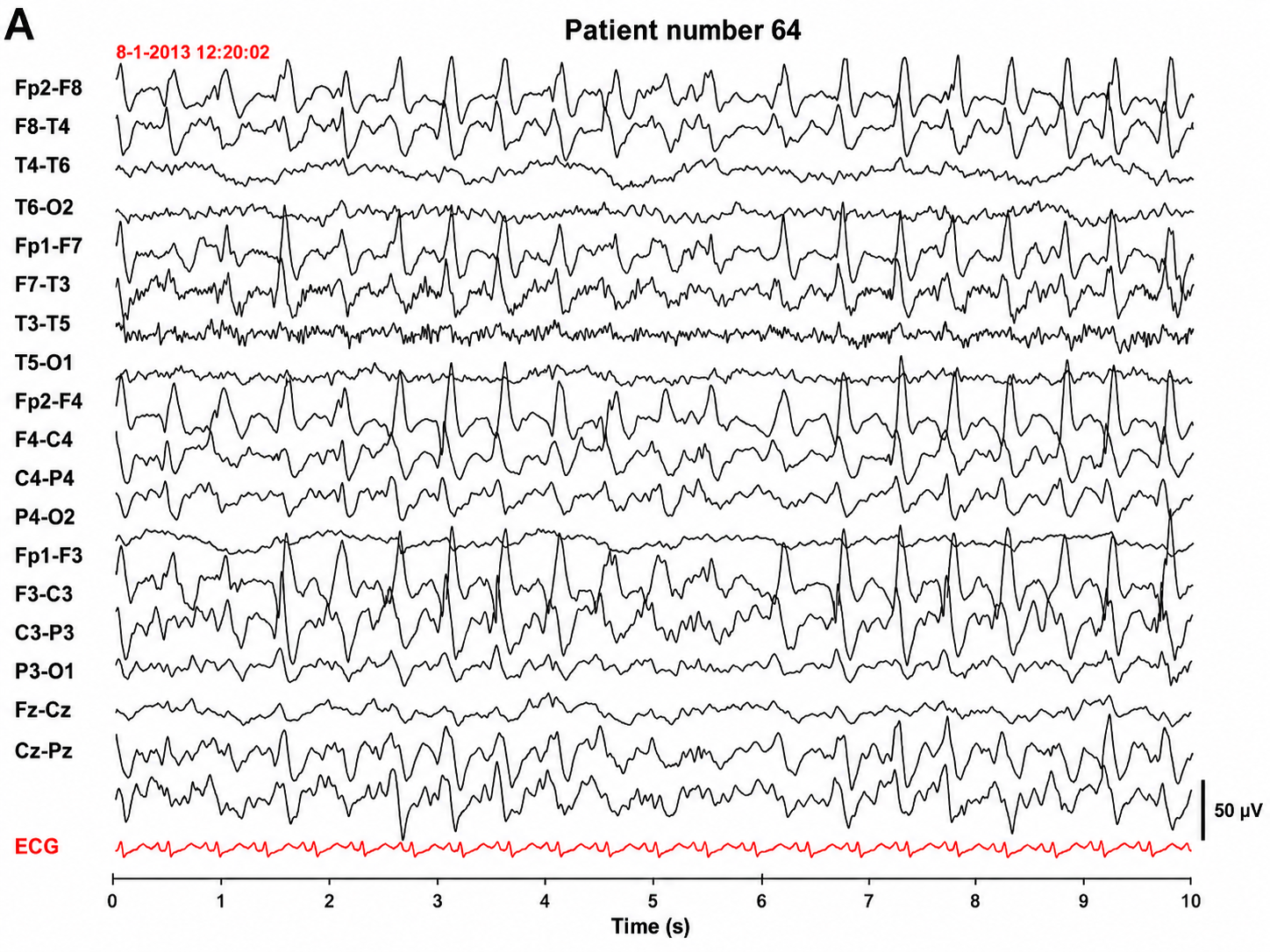
Graphic © Epilepsy & Behavior.
Lateralized periodic paroxysmal patterns differ from generalized periodic paroxysmal patterns in their unilateral distribution. Both patterns share the same waveform morphology (Fisch, 1999).
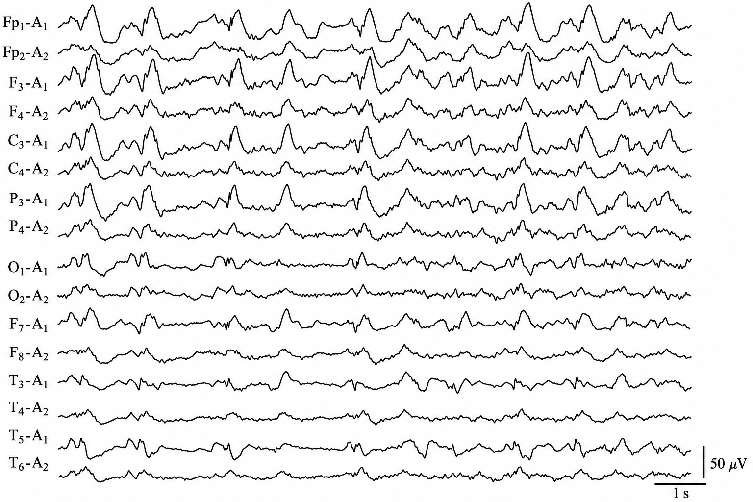
Graphic © Internal Medicine.
Clinical Application
Imagine recording a hyperactive child whose constant movement contaminates every channel. Because a valid brain map needs at least a minute of artifact-free data, and ideally 2 to 5 minutes, drawn from a substantially longer recording, you may find that none of the channels is usable and that the assessment must be repeated. When only a few channels are contaminated, you can base the assessment on the clean channels instead (Demos, 2019). Talking to the client every minute or two, and mentioning how much time remains, helps maintain alertness and reduces drowsiness artifact during longer recordings. Planning for artifact in advance, rather than discovering it afterward, protects the validity of everything built on the raw EEG.
Key Takeaways
A valid brain map depends on clean raw EEG: at least 1 minute of artifact-free data and ideally 2 to 5 minutes, selected separately for eyes-open and eyes-closed conditions from a much longer raw record. Learn to recognize and reproduce common artifacts so you can prevent them, disable low-pass and high-pass filters while editing, and watch for the subtle shift into Stage 1 sleep marked by decreasing alpha and increasing theta. Abnormal EEG patterns fall into abnormal slow activity, paroxysmal epileptogenic abnormalities, and abnormal periodic paroxysmal patterns. These patterns are distinguished by their frequency, distribution, symmetry, and whether they are intermittent or persistent, focal or generalized. Recognizing them, and distinguishing them from benign activity, is essential for valid assessment and safe practice.
Check Your Understanding
- How much artifact-free data do the published qEEG guidelines require for a valid brain map, and how long should the raw recording be?
- What EEG changes signal that a client has drifted into Stage 1 sleep?
- What are the three broad categories of abnormal EEG patterns?
- How do focal and generalized intermittent slow activity differ?
- Why is it useful to intentionally reproduce common artifacts during training?
Descriptive Terms
Use the American Clinical Neurophysiology Society scales, since these are the terms a trained reviewer expects to read. Amplitude is classified as very low (less than 20 µV), low (20-49 µV), medium (50-149 µV), and high (150 µV or greater). Duration is described as very brief (less than 10 s), brief (10-59 s), intermediate duration (1-9.9 min), long (10-59 min), and very long (1 hour or more). Both scales are exhaustive by design, with no gap between adjacent bins (Hirsch et al., 2021).
Common EEG Acronyms for Rhythmic and Periodic Patterns
The common EEG acronyms reviewed in this section include LPDs, BIPDs, GPDs, GRDA, IRDA, LRDA, PLEDs, BIPLEDs, FIRDA, GPEDs, Mf, SIRPIDs, and SW. Read the list with one thing in mind: several of these are not different patterns but the same pattern under two names. When the American Clinical Neurophysiology Society standardized critical-care terminology, PLEDs became LPDs, BIPLEDs became BIPDs, GPEDs became GPDs, and FIRDA was absorbed into a described form of GRDA (Hirsch et al., 2013, 2021). The revision deliberately removed the word epileptiform from purely descriptive labels, because it smuggled an unproven ictal interpretation into what was meant to be a neutral description. The older acronyms are retained here because you will still encounter them in charts and in the literature.
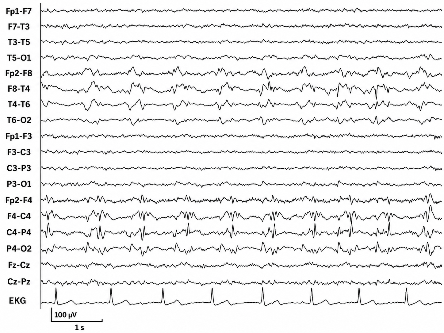
LPDs are lateralized periodic discharges. These unilateral discharges appear as sharp waves or spikes, 100-300 µV, and recur at rates up to 3 Hz (Johnson & Kaplan, 2017).
Graphic © ScienceDirect.
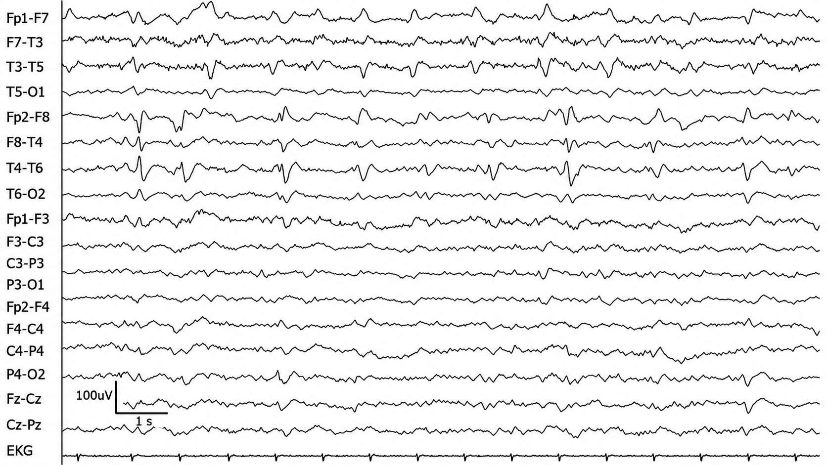
BIPDs are bilateral independent periodic discharges. These asynchronous discharges occur independently in the left and right hemispheres, appear as sharp waves or spikes, 100-300 µV, and recur at rates up to 3 Hz (Johnson & Kaplan, 2017).
Graphic © ScienceDirect.
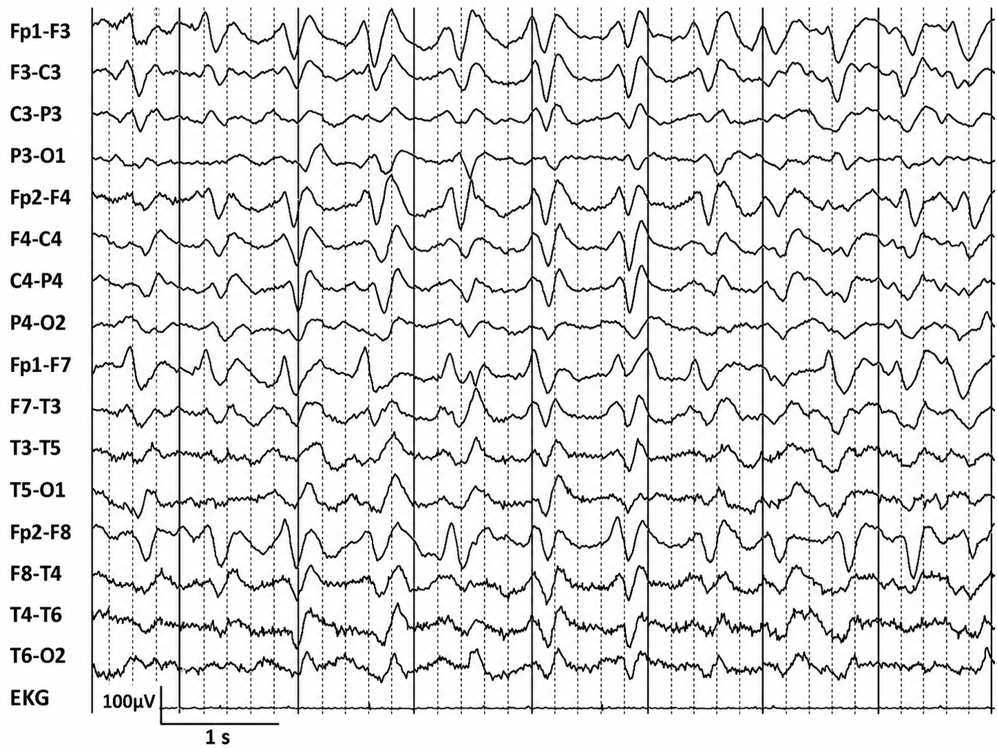
GPDs are generalized periodic discharges. These discharges synchronously occur in both hemispheres, appear as sharp waves or spikes, amplitudes exceed 100 µV, and recur at rates up to 3 Hz (Johnson & Kaplan, 2017).
Graphic © ScienceDirect.
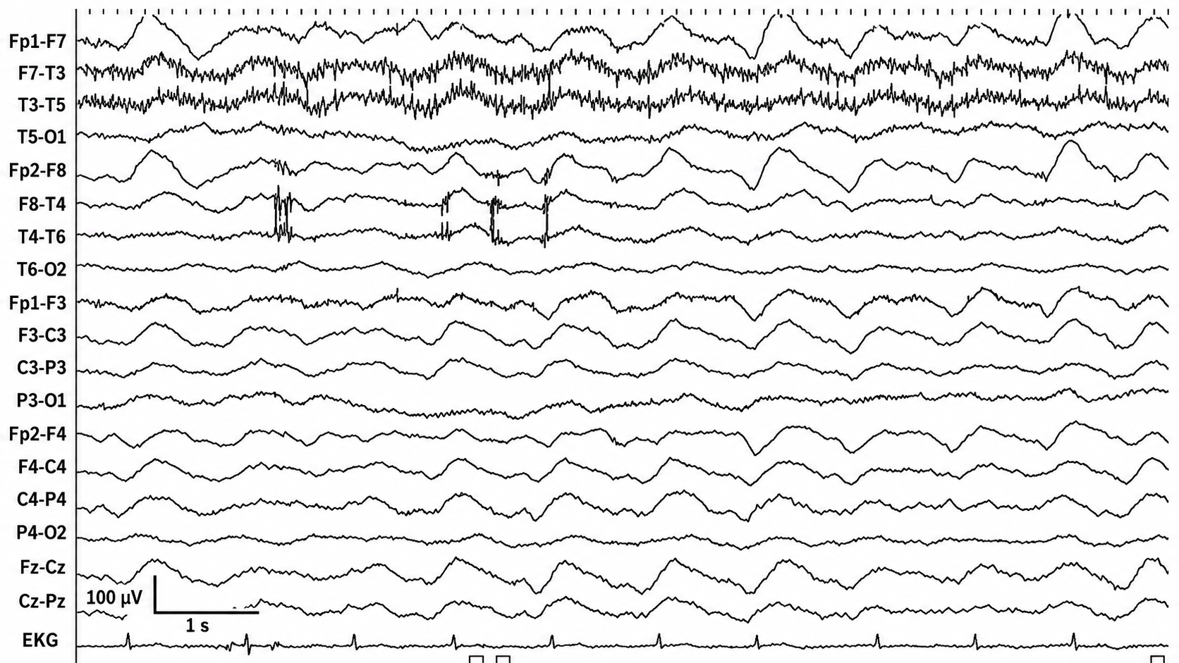
GRDA is generalized rhythmic delta activity. The term frontal intermittent rhythmic delta activity (FIRDA) was used before ACNS standardization in 2012. These bilateral and synchronous discharges exceed 100 µV and recur at rates up to 3 Hz (Johnson & Kaplan, 2017).
Graphic © ScienceDirect.
For focal patterns, describe the location with R (right), L (left), A (anterior), and P (posterior).
IRDA is intermittent rhythmic delta activity. These bilateral synchronous discharges recur between 2-2.5 Hz and appear in brief bursts.
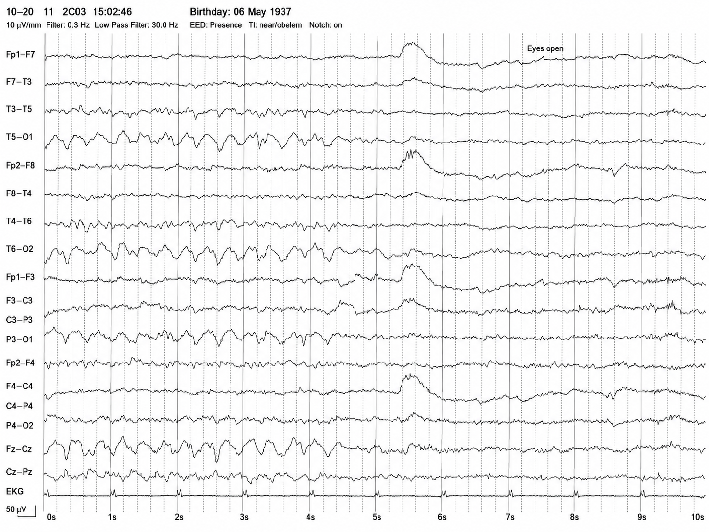
We adapted this graphic from © Richardson and Benbadis (2019). A 10-second page of longitudinal bipolar EEG from an older adult. Rhythmic slow activity appears in the posterior and midline chains (T5-O1, T6-O2, P3-O1, P4-O2, Fz-Cz, Cz-Pz) during the first five seconds. The smooth, frontally maximal deflection just after the 5-second mark is an eye-movement artifact marking the “Eyes open” annotation, and the rhythmic slowing attenuates once the eyes are open. Note that this is not a posterior dominant rhythm: a PDR lies in the alpha band, whereas this activity is far slower. A slow rhythm that reacts normally to eye opening is easy to mistake for alpha, so judge the frequency against the time axis rather than by the reactivity alone.
LRDA is lateralized rhythmic delta activity. These unilateral discharges recur at rates up to 3 Hz. LRDA runs typically last less than 1 minute and are shorter than LPDs (Johnson & Kaplan, 2017).
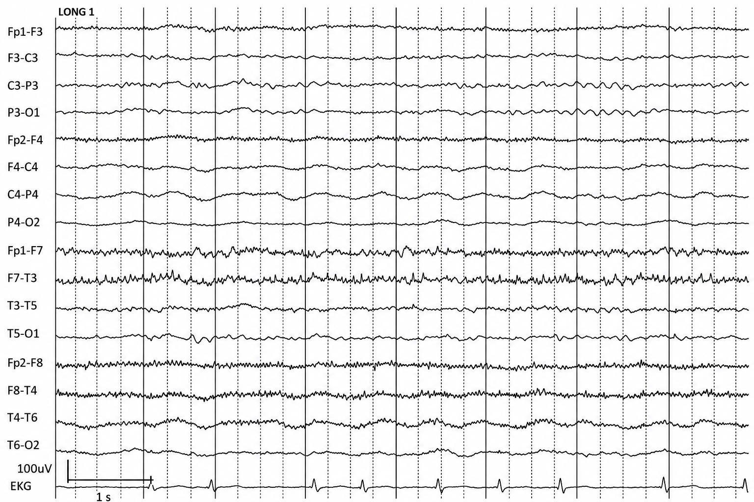
Graphic © ScienceDirect.
PLEDs are periodic lateralized epileptiform discharges. They are lateralized or focal and exhibit regular periodic, negative spike-and-sharp wave patterns with a 20-1000 ms duration and 50-300 µV amplitude.
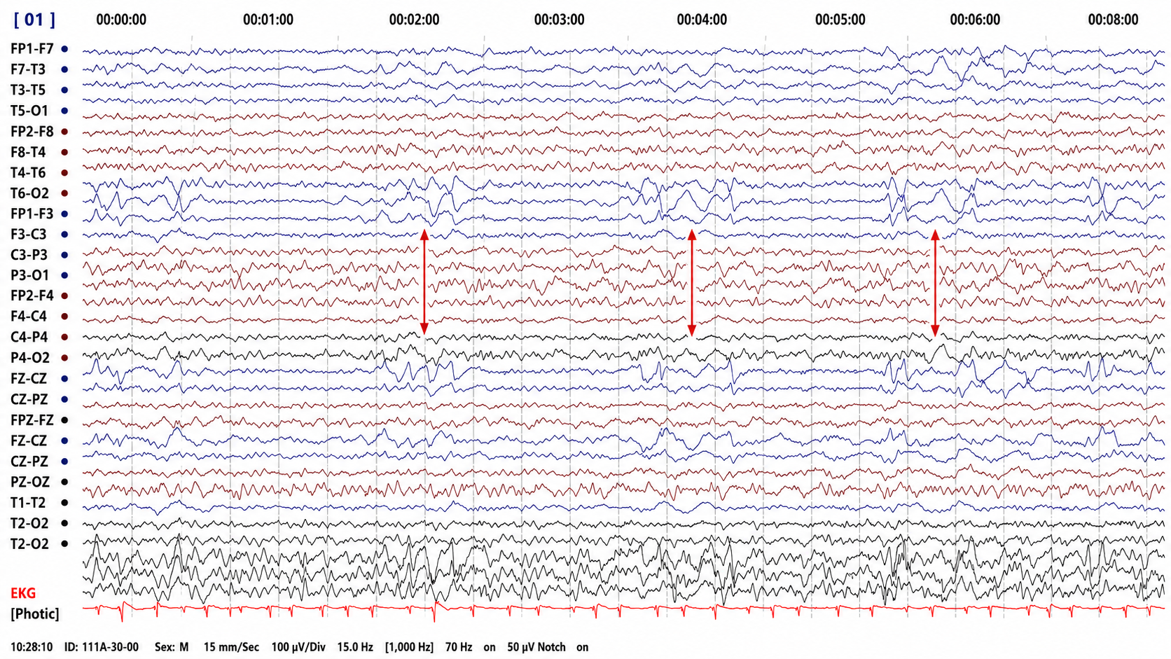
A compressed-timebase recording (15 mm/s) with vertical arrows marking the derivations of interest. Read the timebase before the waveforms. Periodic discharges are defined by a repetition rate of roughly 0.5 to 3 Hz and must persist for at least six cycles, so individual discharges cannot be resolved at this scale, and the spacing between arrows does not represent the discharge interval. Confirm periodicity on a conventional page of a few seconds before applying the label.
BIPLEDs are bilateral independent periodic lateralized epileptiform discharges. They are asynchronous discharges that occur independently in both hemispheres, appear as sharp waves or spikes, 40-100 µV in bipolar montages, and recur at rates from 0.5-1.5 Hz.
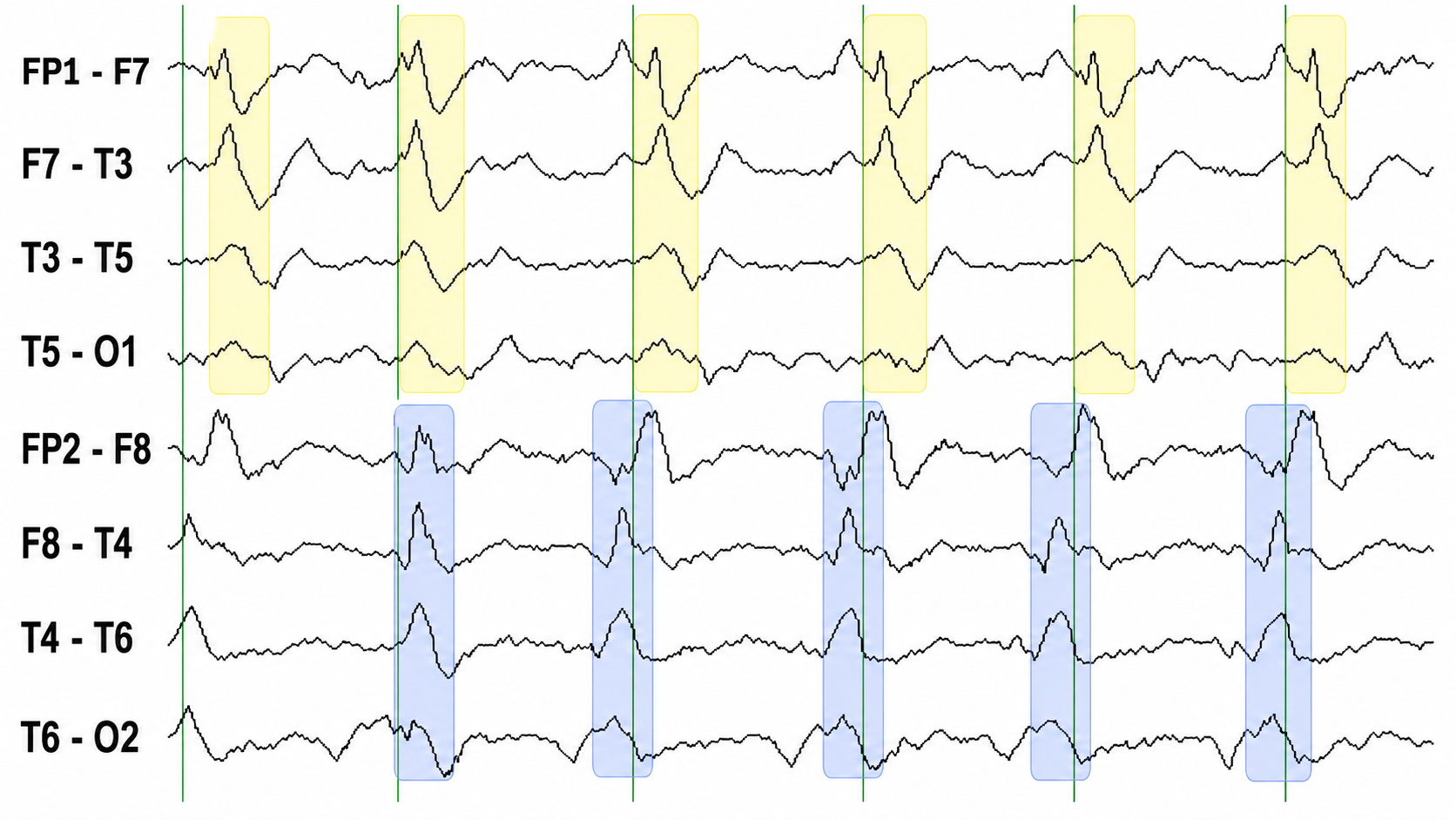
Left temporal discharges are boxed in yellow and right temporal discharges in blue, with vertical lines as timing markers. The defining feature of a bilateral independent pattern is that the two sides are periodic but not synchronous: each temporal region discharges on its own schedule, so left-sided and right-sided events fall at different instants. Checking the timing of one side against the other, rather than simply noting that both sides have discharges, is what separates two independent foci from a single bilaterally synchronous event.
FIRDA is frontal intermittent rhythmic delta activity. Structural brain lesions and encephalopathy are independently associated with the occurrence of FIRDA. Asymmetric FIRDA may be associated with an underlying brain lesion.
FIRDA appears more common than previously reported and is associated with various lesions and encephalopathic conditions. However, FIRDA may also occur in otherwise healthy subjects during hyperventilation. FIRDA occurrence should prompt investigations for toxic-metabolic disturbances and structural lesions (particularly if asymmetric) but does not suggest an epileptic risk.
Graphic © eegatlas-online.com.
GPEDs (or GPDs) are generalized periodic epileptiform discharges.
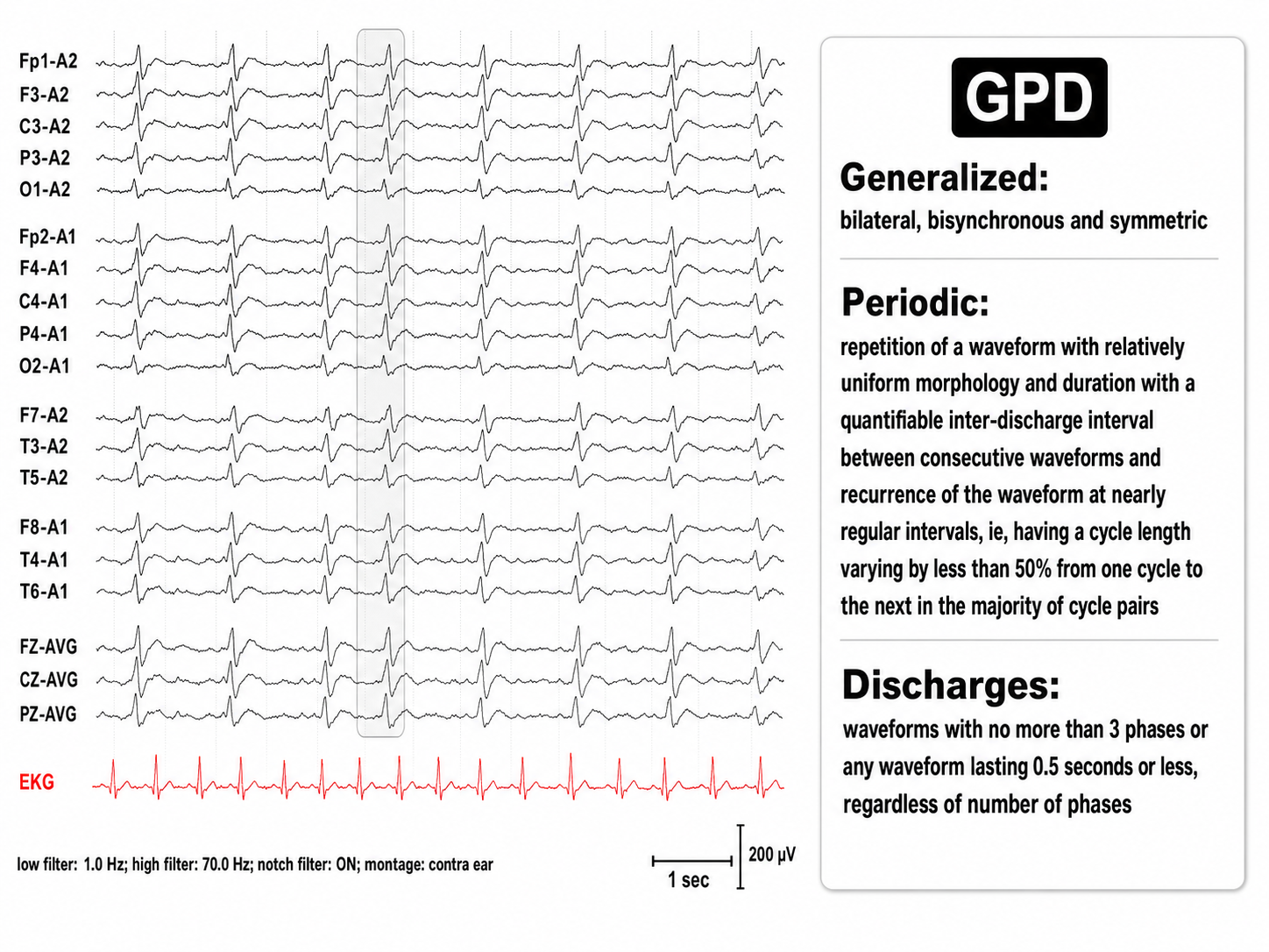
Graphic © eegatlas-online.com.
Multifocal (Mf)
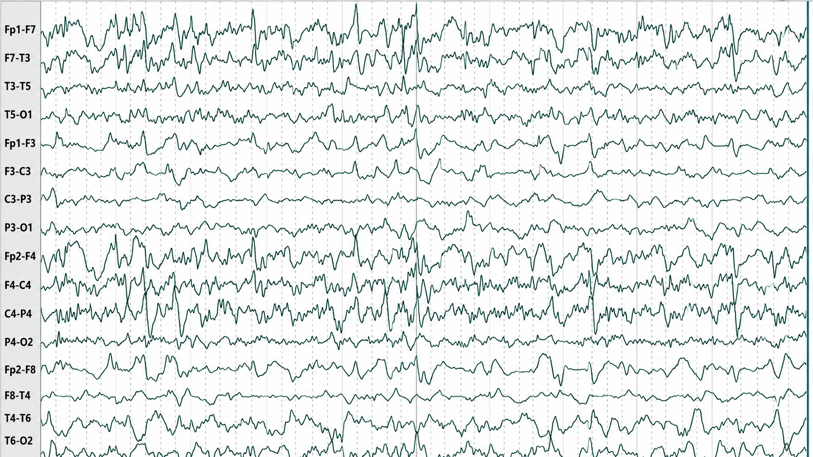
Graphic © Tai-Tong Wong.
SIRPIDs are stimulus-induced rhythmic, periodic, or ictal discharges.
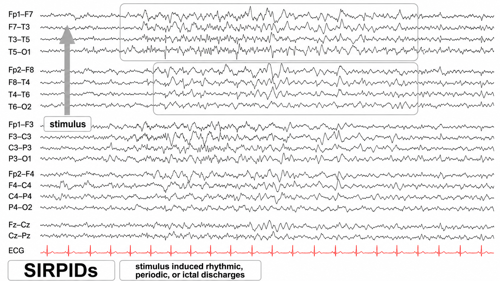
Graphic © eegatlas-online.com.
SW is spike-wave or sharp-wave.
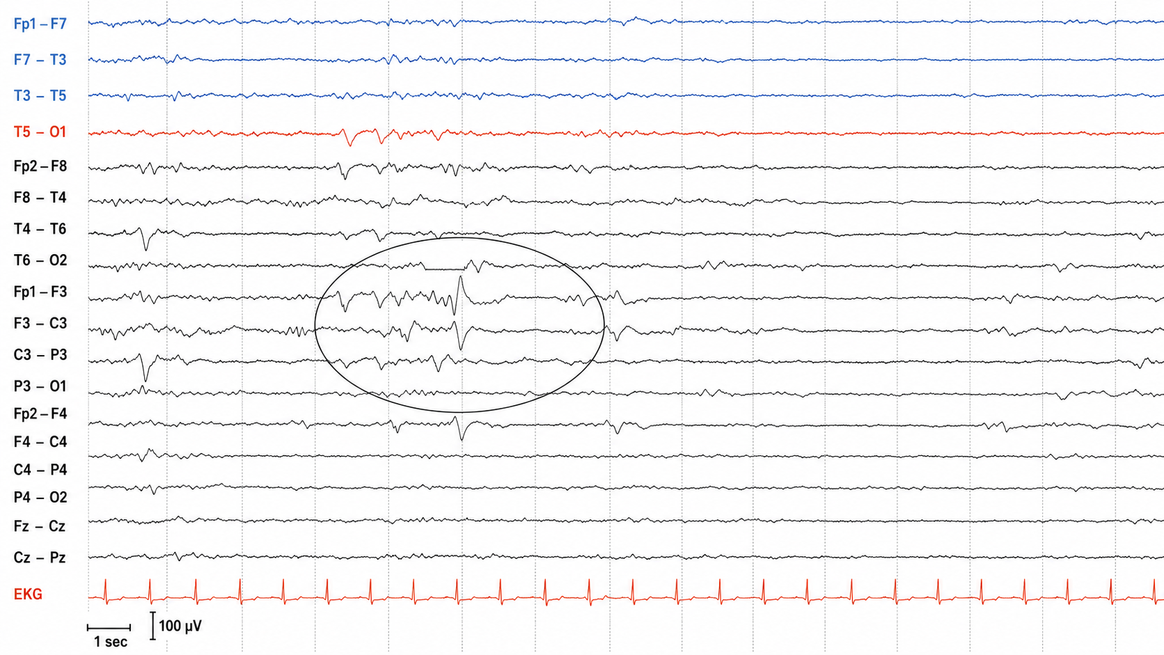
We adapted this graphic from © eegatlas-online.com. A longitudinal bipolar page in which a brief run of sharp, higher-amplitude activity is circled against an otherwise low-voltage background, maximal over the left central and parasagittal chains. Duration is what separates the two transients this acronym covers: a spike lasts 20 to under 70 ms and a sharp wave 70 to 200 ms, so measure the waveform against the 1-second marker rather than judging by how pointed it looks.
Generally Benign EEG Activity
Generally benign EEG activity includes BETS, POSTS, RMTD, SREDA, and wicket waves.
BETS are benign epileptiform transients of sleep. This activity is also called BSSS for benign small sharp spikes or benign sporadic sleep spikes. Sharp waves are seen alone or as a low-amplitude spike and a smaller after-going slow wave. BETS can be monophasic or diphasic and occur during light sleep. There is no disturbance of background activity, and it does not progress. BETS often appears in an ear reference, and when seen elsewhere, it is due to reference contamination. BETS are seen in adults during drowsiness, but they disappear in deeper sleep.
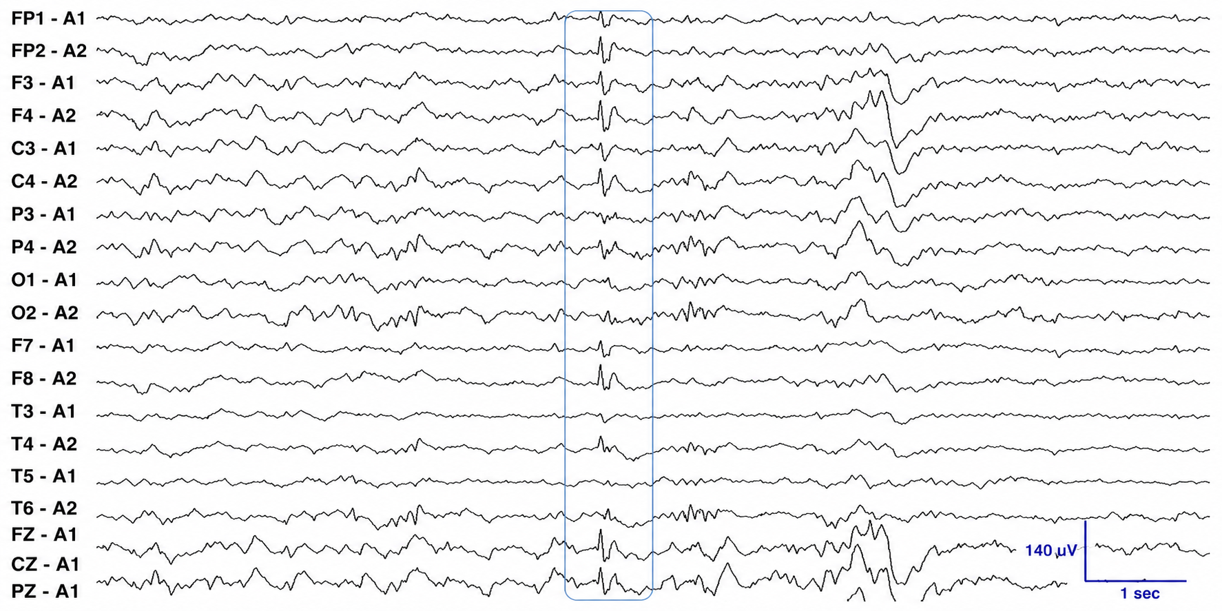
A referential montage in which every channel is referred to an earlobe (A1 or A2); the boxed transient appears in nearly all channels at once. That apparent whole-head distribution is the teaching point, and it is a montage effect rather than a generalized discharge. Because the transient arises at or near the ear, and the ear is the reference for every channel, it propagates into all of them; recorded in a bipolar montage the same event would appear as the small, brief, temporally maximal spike it is. Two features distinguish it from an epileptiform discharge: its low amplitude, and the absence of a prominent aftergoing slow wave.
POSTS are positive occipital sharp transients of sleep. They are sharply contoured surface-positive transients with a frequency of 4-5 Hz, seen alone or in groups over occipital areas. POSTS are bilaterally synchronous though frequently asymmetric in amplitude between the two sides; in bipolar chains they produce a phase reversal at O1 or O2.
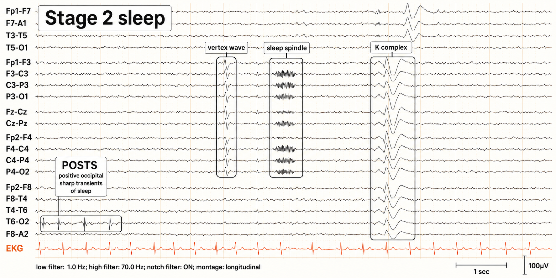
Graphic © eegatlas-online.com. A Stage 2 sleep page labeling four features at once: POSTS in the occipital derivations at lower left, plus a vertex wave, a sleep spindle, and a K complex. Locate the POSTS box before reading the rest.
RMTD is the rhythmic temporal theta of drowsiness. Bitemporal left is greater than right in this longitudinal bipolar montage. Noted are notched rhythmic waveforms localized to the temporal regions, some of which are sharply contoured. This rhythm was formerly referred to as the “psychomotor variant,” which can be differentiated from an epileptiform discharge by its relatively monomorphic appearance, lack of clinical accompaniment, and lack of spatiotemporal evolution.
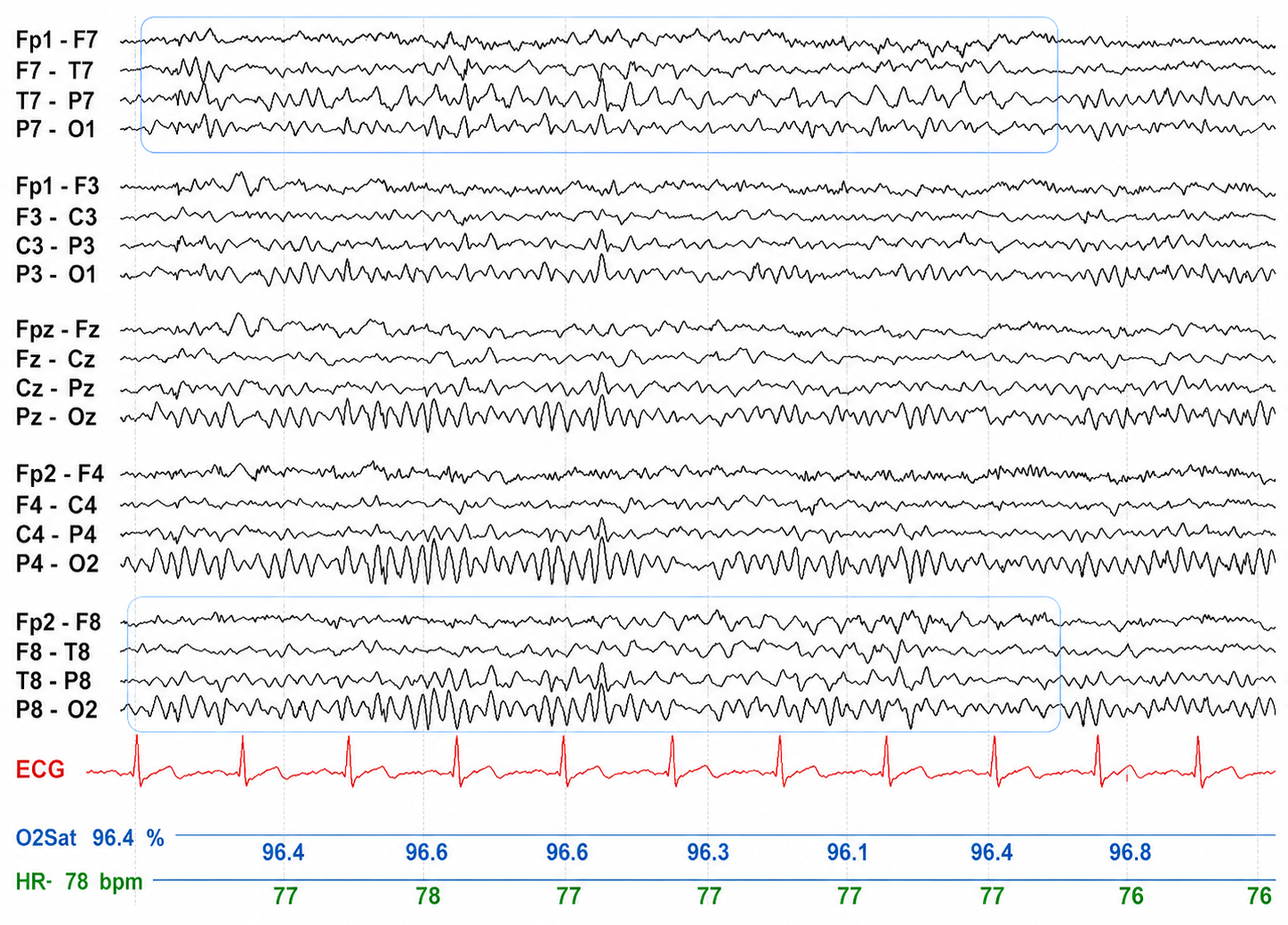
Graphic © Mayo Foundation for Medical Education and Research. Figure courtesy of Jeffrey W. Britton, MD.
SREDA (or SCREDA) is sub-clinical rhythmic electrographic discharges in adults. In the bilateral synchronous parieto-temporal sharp theta rhythm graphic below, black arrows show the onset of periodic posterior-predominant sharply contoured waveforms. The waveforms become rhythmic and then resolve at the latter portion of the figure.
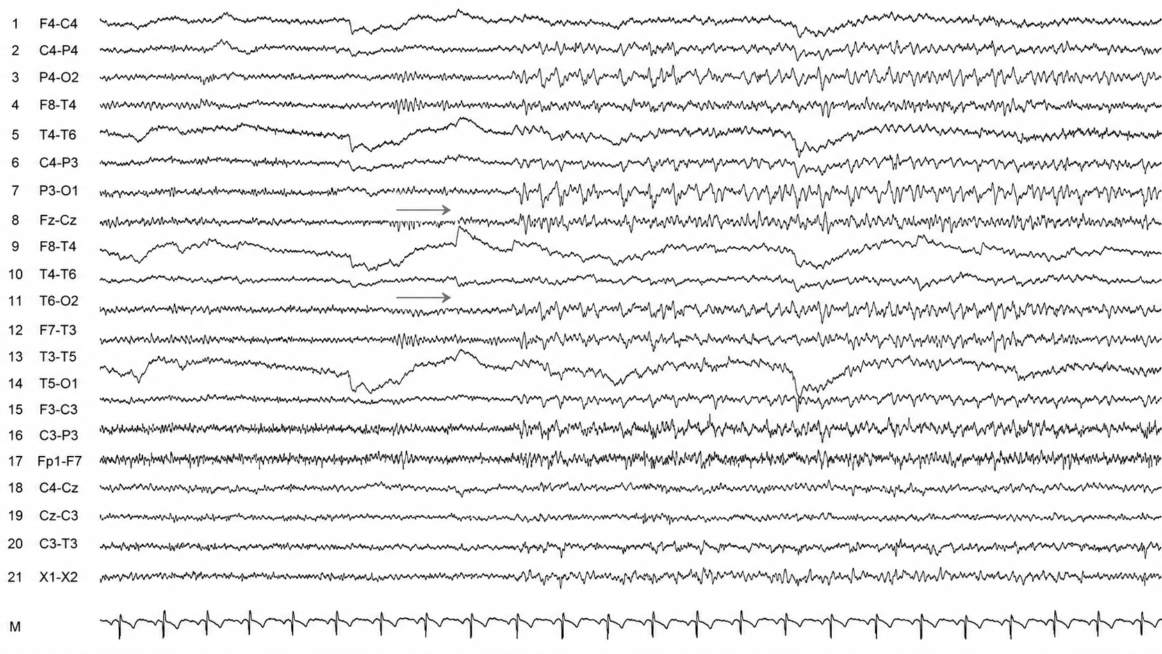
Arrows mark the onset of a sharply contoured, posterior-predominant rhythmic theta discharge that builds across the page. This is SREDA, and it is benign. It is worth studying precisely because it mimics an electrographic seizure and is frequently mistaken for one. Three features separate them: SREDA shows some change in frequency but no spatial or topographic evolution, it produces no clinical change on response testing, and it is not followed by postictal slowing. Calling this tracing a seizure is exactly the error the pattern exists to teach you to avoid.
Wicket waves exhibit an arciform appearance, no after-going slow wave, and no background disruption or disturbance. The wicket waves in the graphic below are seen in the left temporal region with phase-reversal at T7 in seconds 3 and 4 of the tracing using longitudinal bipolar montage.
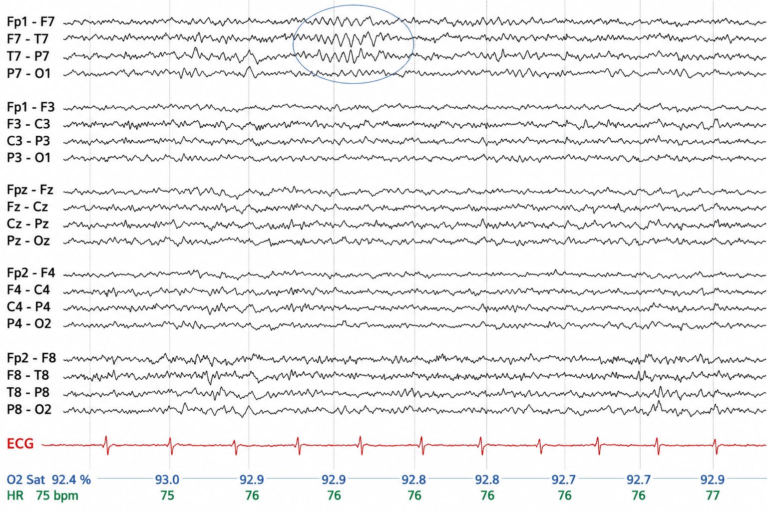
Graphic © Mayo Foundation for Medical Education and Research. Figure courtesy of Jeffrey W. Britton, MD.
Cutting-Edge Topics in EEG Instrumentation
Standardizing the Language of Rhythmic and Periodic Patterns
Much of the terminology in this chapter is being harmonized. Before the American Clinical Neurophysiology Society standardized its critical-care EEG terminology in 2012, overlapping labels such as FIRDA competed with descriptions like generalized rhythmic delta activity. The current scheme classifies patterns by their distribution, whether generalized, lateralized, bilateral independent, or multifocal, and by whether they are periodic or rhythmic, yielding acronyms such as GRDA, LRDA, LPDs, BIPDs, and GPDs. Consistent terminology improves communication between clinicians and researchers and makes findings easier to compare and reproduce.
Infection Control and the End of Routine Skin Abrasion
Site preparation is undergoing a quieter revolution. The traditional push to abrade the skin below 5 Kohms is giving way to gentler preparation, both because modern high-input-impedance amplifiers tolerate higher impedances and because abrasion carries an infection risk (Ferree et al., 2001; Kappenman & Luck, 2010). The COVID-19 pandemic accelerated this shift and left behind a durable emphasis on hand hygiene, risk-based selection of personal protective equipment, and rigorous cleaning of caps, cables, and sensors. These aseptic measures, detailed in the Aseptic Techniques unit, have outlasted the pandemic, though the guidance now stresses matching protection to assessed risk rather than layering it on universally.
Glossary
A (auricular): the International 10-20 system letter designating an earlobe reference placement, as in A1 and A2.
abnormal periodic paroxysmal patterns: EEG discharges that recur at nearly regular intervals, either generalized or lateralized to one hemisphere, signaling acute cerebral dysfunction; current terminology calls these generalized and lateralized periodic discharges.
abnormal slow activity: delta or theta activity appearing during wakefulness where faster rhythms are expected, occurring intermittently or persistently and either generalized or focal, and indicating cerebral dysfunction.
active electrode: an electrode positioned at a measurement site whose potential contributes to the recorded differential signal; it is distinct from the reference and ground electrodes.
amplitude: the magnitude of a signal's excursion from a specified reference level, reported using a stated convention such as peak, peak-to-peak, or RMS.
artifact: an unwanted signal component introduced by movement, environmental interference, hardware, processing, or biological activity outside the signal of interest.
benign epileptiform transients of sleep (BETS): sharp waves seen alone or as a low-amplitude spike with a smaller after-going slow wave, monophasic or diphasic, that occur during light sleep without disturbing background activity and do not progress.
benign small sharp spikes (BSSS): another name for benign epileptiform transients of sleep.
bilateral independent periodic discharges (BIPDs): asynchronous discharges that occur independently in the left and right hemispheres, appear as sharp waves or spikes, measure 100-300 µV, and recur at rates up to 3 Hz.
bilateral independent periodic lateralized epileptiform discharges (BIPLEDs): asynchronous sharp waves or spikes recurring independently over each hemisphere at 0.5-1.5 Hz and 40-100 µV in bipolar montages; renamed bilateral independent periodic discharges (BIPDs) in the ACNS 2021 terminology.
bridging artifact: electrical coupling between adjacent electrodes caused by conductive gel, sweat, or moisture, reducing their independence and distorting recorded voltage differences.
brief duration: the ACNS duration category for rhythmic or periodic EEG patterns lasting 10-59 seconds.
C fibers: small unmyelinated afferent fibers conducting slowly, commonly about 0.5 to 2 m/s, and carrying polymodal nociceptive, thermal, pruritic, and autonomic information.
channel: one differential amplifier input, formed by a pair of electrodes whose voltage difference is recorded. A single ground electrode is shared across all channels rather than belonging to any one of them.
conductive gel: a liquid or semi-liquid electrolyte that bridges scalp and electrode to lower and stabilize impedance; used to fill the wells of a wet cap.
conductive paste: a thicker electrolyte, such as Ten20™, that both conducts and helps hold a cup electrode in place on the scalp.
drowsiness artifact: the intrusion of drowsiness or light sleep into a recording intended to sample wakefulness, marked by attenuation of the posterior dominant rhythm, slow rolling eye movements of opposite polarity at F7 and F8, and 1-2 Hz alpha slowing.
dry electrode: an electrode designed to record without conventional conductive gel or paste, often using direct contact, pins, or capacitive coupling.
EEG artifacts: noncerebral electrical activity in an EEG recording, which can be divided into physiological and exogenous artifacts.
electro-ocular artifact: contamination of EEG recordings by potentials generated by eye blinks, eye flutter, and eye movements.
electrode cap: a head-worn array that positions EEG electrodes at standardized or predefined scalp locations.
electrode impedance meter: an instrument that applies a small test signal to estimate electrode-skin impedance.
electrode-pop artifact: an abrupt high-amplitude transient caused by a sudden change in electrode-skin contact potential or impedance.
EMG artifact (ECG): false or obscured ECG events caused by skeletal-muscle electrical activity, potentially producing spurious or missed beat detections.
epileptogenic patterns of doubtful significance: brief EEG patterns not associated with seizures or neurological disorders, such as 6-Hz spike-and-slow-wave, 14- and 6-Hz positive bursts, benign epileptiform transients of sleep (BETS), rhythmical mid-temporal discharge (RMTD), small sharp spikes (SSS), and wicket spikes.
exogenous artifact: signal contamination originating outside the organism, such as electromagnetic interference, vibration, or recording-equipment noise.
F (frontal): the International 10-20 system letter designating sites that detect frontal lobe EEG activity.
focal and lateralized intermittent slow activity: EEG activity under 8 Hz usually confined to a single electrode or a couple of adjacent electrodes. These bursts have an irregular appearance, are composed of several frequencies, and rarely involve an entire hemisphere.
Fp electrode sites: frontopolar scalp locations designated Fp1, Fpz, and Fp2 in the international 10–10 system; the 10–20 system uses Fp1 and Fp2.
frontal intermittent rhythmic delta activity (FIRDA): a waxing-and-waning pattern of rhythmic delta waves appearing intermittently over the frontal regions, termed frontally predominant generalized rhythmic delta activity under current ACNS terminology; it most often signals metabolic encephalopathy.
generalized intermittent slow activity: asynchronous EEG activity under 8 Hz that involves the majority or all of both hemispheres. These bursts typically consist of polymorphic delta.
generalized periodic discharges (GPDs): repetitive, broadly distributed epileptiform-appearing waveforms that recur at regular intervals, often with a triphasic morphology. They are common in toxic and metabolic encephalopathies and require clinical correlation rather than a presumption of epilepsy.
generalized periodic epileptiform discharges (GPEDs): the pre-2012 name for generalized periodic discharges (GPDs); periodic sharp waves or spikes occurring synchronously in both hemispheres. Not a separate pattern from GPDs.
generalized periodic paroxysmal patterns: epileptiform discharges in the same areas of both hemispheres. The waveforms exhibit similar composition, amplitude, and phase in each hemisphere but may vary slightly within a hemisphere.
generalized rhythmic delta activity (GRDA): rhythmic delta waves under 4 Hz occurring bilaterally and synchronously over both hemispheres; the frontally predominant form replaced the older label FIRDA in the 2012 ACNS nomenclature.
ground electrode: an electrode connected to the recording system's common or driven-ground circuit to reduce common-mode interference; it is distinct from the reference electrode.
hertz (Hz): the SI unit of frequency equal to one cycle per second.
high amplitude: 150 µV or greater on the ACNS scale.
ictal epileptiform discharges: discharges occurring during a seizure, which may include 3-Hz spike-and-wave, slow spike-and-wave, sharp-and-slow-wave discharges, amplitude and frequency fluctuations in rhythms of 10 Hz or higher, and irregular multiple spike-and-wave discharges.
impedance (Z): frequency-dependent opposition to alternating current, comprising resistance and reactance and measured in ohms.
impedance test: measurement of electrode-skin impedance before or during biopotential recording.
inion: the most prominent point of the external occipital protuberance at the posterior skull.
interictal epileptiform discharges: individual spikes and sharp waves, and complexes containing both waveforms, that last less than 2 s and occur between seizures.
intermediate duration: 1-9.9 minutes on the ACNS scale.
intermittent rhythmic delta activity (IRDA): bilateral synchronous discharges that recur between 2-2.5 Hz and appear in brief bursts.
international 10–20 system: a standardized method for locating EEG electrodes at intervals of 10% or 20% of measured head distances; the original array includes 19 scalp and two auricular sites, with ground specified separately.
lateralized periodic discharges (LPDs): unilateral discharges that appear as sharp waves or spikes, measure 100-300 µV, and recur at rates up to 3 Hz.
lateralized periodic paroxysmal patterns: epileptiform discharges that differ from generalized periodic paroxysmal patterns in their unilateral distribution. Both patterns share the same waveform morphology.
lateralized rhythmic delta activity (LRDA): unilateral discharges that recur at rates up to 3 Hz. LRDA runs typically last less than 1 minute and are shorter than LPDs.
long duration: 10-59 minutes on the ACNS scale.
low amplitude: 20-49 µV on the ACNS scale.
mastoid bone: the bony prominence behind the ear.
medium amplitude: 50-149 µV on the ACNS scale.
microvolt (µV): a unit of electric potential equal to 10⁻⁶ volt.
Modified Combinatorial Nomenclature: the 10-10 naming system that relabels the temporal sites T3/T4 as T7/T8 and T5/T6 as P7/P8 for finer, more consistent electrode positions.
montage: the specified arrangement of electrode derivations or channel pairings used to display a physiological recording.
movement artifact: signal distortion caused by movement of the person, sensor, electrode, cable, or tissue interface; its appearance and effects depend on recording modality.
multifocal (Mf): an EEG abnormality detected at several scalp locations.
nasion: the midline depression at the junction of the frontal bone and nasal bones.
neuroplasticity: experience- or injury-related change in neural structure, function, connectivity, or representation.
notch filter: a band-stop filter that strongly attenuates a narrow frequency range, commonly centered on 50 or 60 Hz.
O (occipital): the International 10-20 system letter designating sites that detect occipital lobe EEG activity.
ohm (Ω): the unit of impedance or resistance.
parietal EEG site (P): an electrode location over the parietal scalp designated P in international EEG-placement systems.
paroxysmal epileptogenic abnormalities: interictal epileptiform discharges, both focal and generalized, ictal discharges, secondary bilateral synchrony, and epileptiform patterns of doubtful significance.
periodic lateralized epileptiform discharges (PLEDs): lateralized or focal discharges with regular periodic negative spike-and-sharp wave patterns of 20-1000 ms duration and 50-300 µV amplitude, now termed lateralized periodic discharges (LPDs) in ACNS terminology.
physiological artifact: contamination generated by biological activity other than the target signal, such as eye, muscle, cardiac, respiratory, or sweat activity.
positive occipital sharp transients of sleep (POSTS): sharply contoured surface-positive transients at 4-5 Hz, seen alone or in groups over occipital areas.
posterior dominant rhythm (PDR): the dominant occipital rhythm during relaxed wakefulness with eyes closed, usually in the alpha range in healthy adults and attenuated by eye opening.
preauricular point: a landmark immediately anterior to the tragus used in cranial and EEG measurements.
pulse artifacts: noncerebral voltages due to the mechanical movement of an electrode in relation to the skin surface caused by the pressure wave of each heartbeat.
quantitative EEG (qEEG): the numerical analysis of digitized EEG features, such as spectral power, asymmetry, and connectivity, sometimes compared with normative databases; no universal minimum channel count defines it.
reference electrode: an electrode whose potential is used as the comparison for an active recording electrode; it is distinct from the ground electrode.
rhythmic temporal theta of drowsiness (RMTD): a benign drowsiness variant consisting of notched, sometimes sharply contoured rhythmic theta waveforms over the midtemporal regions, without epileptiform significance.
salt bridge: an unintended conductive path formed when excess gel or paste connects two neighboring electrodes, merging their signals into one and making both channels unusable; the mechanism behind the bridging artifact.
secondary bilateral synchrony (SBS): generalized, bilaterally synchronous epileptiform discharges driven by a unilateral focal cortical generator, most often frontal, that spread through transcallosal and subcortical pathways.
sharp wave: an epileptiform transient with a pointed peak and duration of approximately 70 to 200 ms under standard EEG display conditions.
spike-wave (SW): a discharge in which a spike is immediately followed by a slow wave, often recurring in rhythmic trains such as the 3-Hz generalized bursts of absence seizures.
SREDA (or SCREDA): subclinical rhythmic electrographic discharges in adults; a benign posterior-predominant rhythmic sharp theta pattern that mimics an electrographic seizure but shows no spatial evolution, no clinical change on response testing, and no postictal slowing.
stimulus-induced rhythmic, periodic, or ictal discharges (SIRPIDs): EEG discharges reliably produced by alerting stimuli.
tragus: the small cartilaginous flap projecting backward over the opening of the external acoustic meatus; the preauricular point lies immediately anterior to it.
transient (EEG): an isolated waveform or brief sequence that is distinguishable from the ongoing EEG background.
vertex and Cz: the vertex is the highest point of the skull; Cz is the midline EEG position at the intersection of nasion-inion and left-right preauricular measurements.
very brief duration: less than 10 s on the ACNS scale.
very long duration: longer than 1 hour on the ACNS scale.
very low amplitude: less than 20 µV on the ACNS scale.
volume conduction: passive spread of electrical fields through conductive biological tissues, allowing a source to influence electrodes located at a distance.
wet electrode: an electrode that uses conductive gel or paste as the electrolyte between skin and sensor.
wicket waves: EEG activity with arciform appearance, no after-going slow-wave, and no background disruption or disturbance.
Test Yourself on ClassMarker
Click the button below to take a 10-question exam over this entire unit. There is no password.
Review Flash Cards on Quizlet
Click the button below to review our chapter flash cards.
Visit the BioSource Software Website
BioSource Software offers Physiological Psychology, which satisfies BCIA's Neuroanatomy requirement, and the Neurofeedback100 Testing Service, which provides extensive multiple-choice testing over the Neurofeedback Blueprint.

Assignment
Now that you have completed this module, summarize your key talking points when explaining the process of NFT to a client. Which concepts do your clients find most challenging? Which explanations have been most effective?
References
Acharya, J. N., Hani, A. J., Cheek, J., Thirumala, P., & Tsuchida, T. N. (2016). American Clinical Neurophysiology Society Guideline 2: Guidelines for standard electrode position nomenclature. Journal of Clinical Neurophysiology, 33(4), 308-311. https://doi.org/10.1097/WNP.0000000000000316
Association for Applied Psychophysiology and Biofeedback. (2019). About biofeedback. https://aapb.org/About-Biofeedback
Benbadis, S. R., & Rielo, D. A. (2018). Encephalopathic EEG patterns. Medscape. https://emedicine.medscape.com/article/1140530-overview
Collura, T. F. (2014). Technical foundations of neurofeedback. Routledge.
Demos, J. N. (2019). Getting started with neurofeedback (2nd ed.). W. W. Norton & Company.
Ferree, T. C., Luu, P., Russell, G. S., & Tucker, D. M. (2001). Scalp electrode impedance, infection risk, and EEG data quality. Clinical Neurophysiology, 112(3), 536-544. https://doi.org/10.1016/s1388-2457(00)00533-2
Fisch, B. J. (1999). Fisch and Spehlmann's EEG primer (3rd ed.). Elsevier.
Hammond, D. C. (2011). What is neurofeedback: An update. Journal of Neurotherapy, 15(4), 305–336. https://doi.org/10.1080/10874208.2011.623090
Hirsch, L. J., LaRoche, S. M., Gaspard, N., Gerard, E., Svoronos, A., Herman, S. T., Mani, R., Arif, H., Jette, N., Minazad, Y., Kerrigan, J. F., Vespa, P., Hantus, S., Claassen, J., Young, G. B., So, E., Kaplan, P. W., Nuwer, M. R., Fountain, N. B., & Drislane, F. W. (2013). American Clinical Neurophysiology Society's standardized critical care EEG terminology: 2012 version. Journal of Clinical Neurophysiology, 30(1), 1–27. https://doi.org/10.1097/WNP.0b013e3182784729
Hirsch, L. J., Fong, M. W. K., Leitinger, M., LaRoche, S. M., Beniczky, S., Abend, N. S., Lee, J. W., Wusthoff, C. J., Hahn, C. D., Westover, M. B., Gerard, E. E., Herman, S. T., Haider, H. A., Osman, G., Rodriguez-Ruiz, A., Maciel, C. B., Gilmore, E. J., Fernandez, A., Rosenthal, E. S., . . . Gaspard, N. (2021). American Clinical Neurophysiology Society's standardized critical care EEG terminology: 2021 version. Journal of Clinical Neurophysiology, 38(1), 1–29. https://doi.org/10.1097/WNP.0000000000000806
International QEEG Certification Board. (n.d.). Guideline: Minimum technical requirements for performing quantitative EEG. EEG and Clinical Neuroscience Society. https://qeegcertificationboard.org
ISNR Board of Directors. (2010). What is neurofeedback? https://isnr.org/what-is-neurofeedback
Jin, L. (2007). A reappraisal of secondary bilateral synchrony. Neurology Asia, 12, 29-35. http://www.neurologyasia.org/articles/20071_029.pdf
Johnson, E. L., & Kaplan, P. W. (2017). Population of the ictal-interictal zone: The significance of periodic and rhythmic activity. Clinical Neurophysiology Practice, 2, 107-118. https://doi.org/10.1016/j.cnp.2017.05.001
Kappenman, E. S., & Luck, S. J. (2010). The effects of electrode impedance on data quality and statistical significance in ERP recordings. Psychophysiology, 47(5), 888-904. https://doi.org/10.1111/j.1469-8986.2010.01009.x
Khazan, I. Z. (2019). Biofeedback and mindfulness in everyday life: Practical solutions for improving your health and performance. W. W. Norton & Company.
Biofeedback Certification International Alliance. (2020). Neurofeedback essential skills list. https://bcia.memberclicks.net/assets/NFCommonDocs/NF%20Mentoring%20Handbook.pdf
Peper, E., Gibney, K. H., Tylova, H., Harvey, R., & Combatalade, D. (2008). Biofeedback mastery: An experiential teaching and self-training manual. Association for Applied Psychophysiology and Biofeedback.
Richardson, C. A., & Benbadis, S. R. (2019). Generalized EEG waveform abnormalities. Medscape. https://emedicine.medscape.com/article/1140075-overview
Sinha, S. R., Sullivan, L. R., Sabau, D., San-Juan, D., Dombrowski, K. E., Halford, J. J., Hani, A. J., Drislane, F. W., & Stecker, M. M. (2016). American Clinical Neurophysiology Society Guideline 1: Minimum technical requirements for performing clinical electroencephalography. Journal of Clinical Neurophysiology, 33(4), 303-307. https://doi.org/10.1097/WNP.0000000000000308
Khazan, I., Shaffer, F., Moss, D., Lyle, R. R., & Rosenthal, S. (Eds.). (2023). Evidence-based practice in biofeedback and neurofeedback (4th ed.). Association for Applied Psychophysiology and Biofeedback.
Tan, G., Shaffer, F., Lyle, R. R., & Teo, I. (Eds.). (2016). Evidence-based practice in biofeedback and neurofeedback (3rd ed.). Association for Applied Psychophysiology and Biofeedback.
Thompson, M., & Thompson, L. (2015). The biofeedback book: An introduction to basic concepts in applied psychophysiology (2nd ed.). Association for Applied Psychophysiology and Biofeedback.