Electrical and Clinical Safety
What You Will Learn in This Chapter
Fifty milliamperes can stop a heart. That number is the reason this chapter exists, and it is why the electrical concepts here are not academic background but the basis of every precaution you take with a client wired to a mains-powered amplifier.
The chapter builds from the atom up. You will work through charge, current, conductors and insulators, direct and alternating current, electromotive force, voltage, power, resistance, conductance, and Ohm's law, then apply them to impedance, DC offset, and the difference between an open, a closed, and a short circuit.
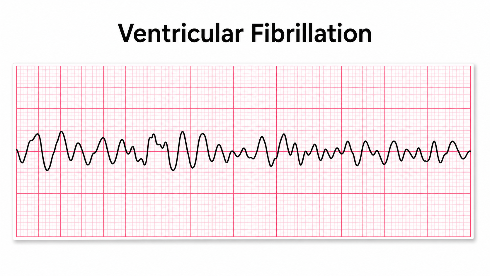
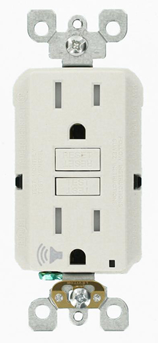
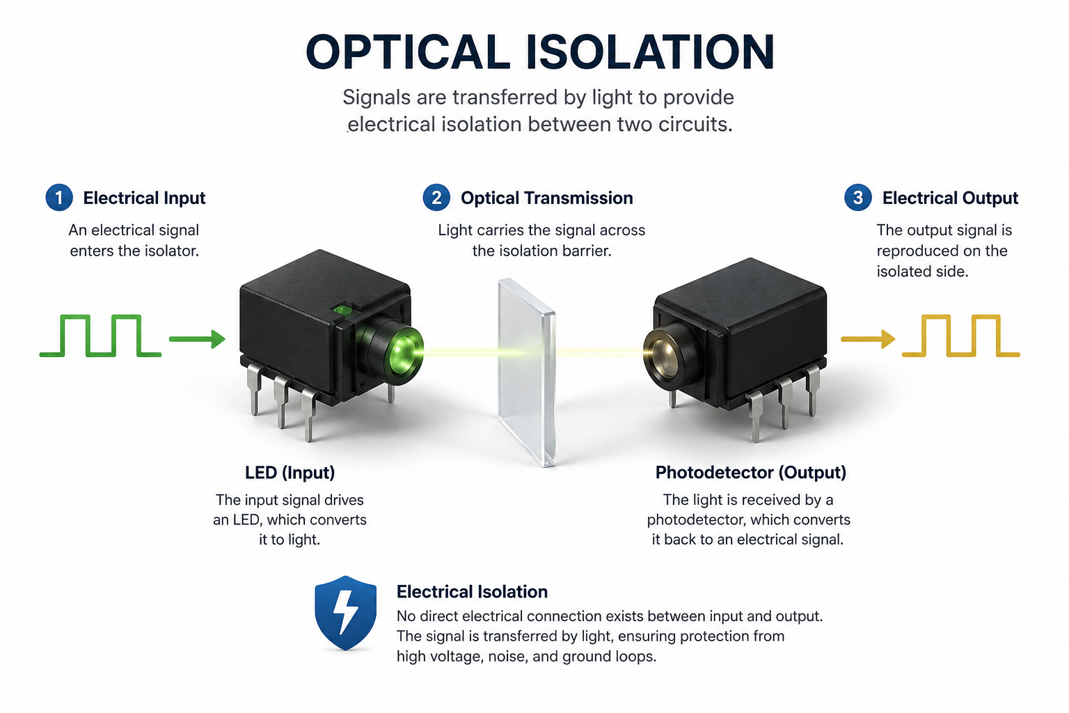
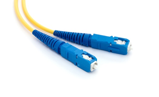
The final section turns to protection: what current does to the body at increasing intensities, and how ground fault interrupt circuits, optical isolation, fiber optic connections, and telemetry keep line current away from the person you are recording.
IQCB Blueprint Coverage: This unit addresses Instrumentation and Electronics: Essential Terms and Concepts (III. Technical), Electrical Measurement and Ohm's Law (III. Technical), and Electrical and Clinical Safety (III. Technical).
Learning Objectives
After completing this section, you will be able to:
Describe the structure of the atom and explain how charge, ions, and electrons relate to biological signals.
Distinguish conductors from insulators and explain how the EEG travels through interstitial fluid by volume conduction.
Compare direct and alternating current and state the unit used to measure each quantity.
Define electromotive force, voltage, and power, and calculate watts from amperes and volts.
State Ohm's law and use it to solve for current, voltage, or resistance.
Distinguish resistance from impedance, and explain how reactance makes impedance frequency dependent.
Explain what an impedance test measures and what values indicate an open or closed circuit.
Distinguish open, closed, and short circuits, and recognize each from an impedance reading.
State the approximate current thresholds for injury, respiratory effects, and fatal ventricular fibrillation, and explain why they vary.
Explain how ground fault interrupt circuits, optical isolation, fiber optic connections, and telemetry protect clients.
Electrical and Clinical Safety
Electricity makes most biofeedback applications possible. Biological signals like skeletal muscle and cortical voltages are streams of charged atoms or molecules called ions.
Listen to the Full-Length Lecture: Part 1
The hardware that monitors these signals is powered by batteries or wall outlets that supply currents of electrons.
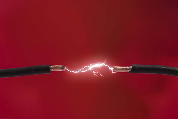
Without a basic understanding of electricity and the circuits used in biofeedback instruments, we might mistakenly accept readings produced by equipment misuse or breakdown. "Garbage in, garbage out."
What This Unit Covers

This unit covers Basic Terms and Metrics, EEG Recording, and Safety Precautions.
Basic Terms and Metrics
Building Blocks of Matter
This section introduces the atomic building blocks relevant to biofeedback, from the structure of atoms to the ions that carry biological signals. These concepts may seem far removed from clinical practice, but they explain why the EEG, SEMG, and electrodermal signals you monitor behave the way they do.
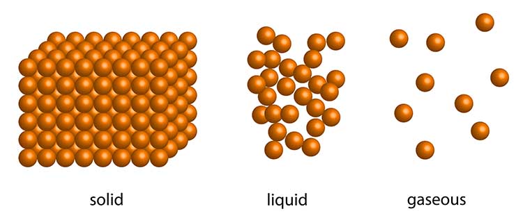
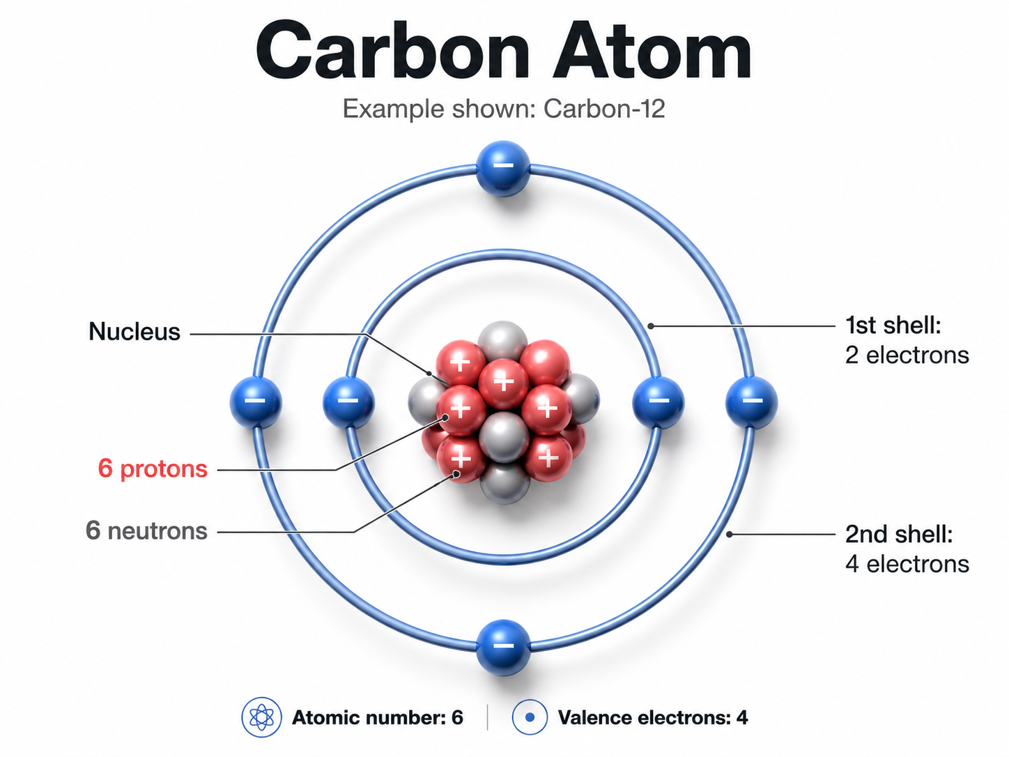
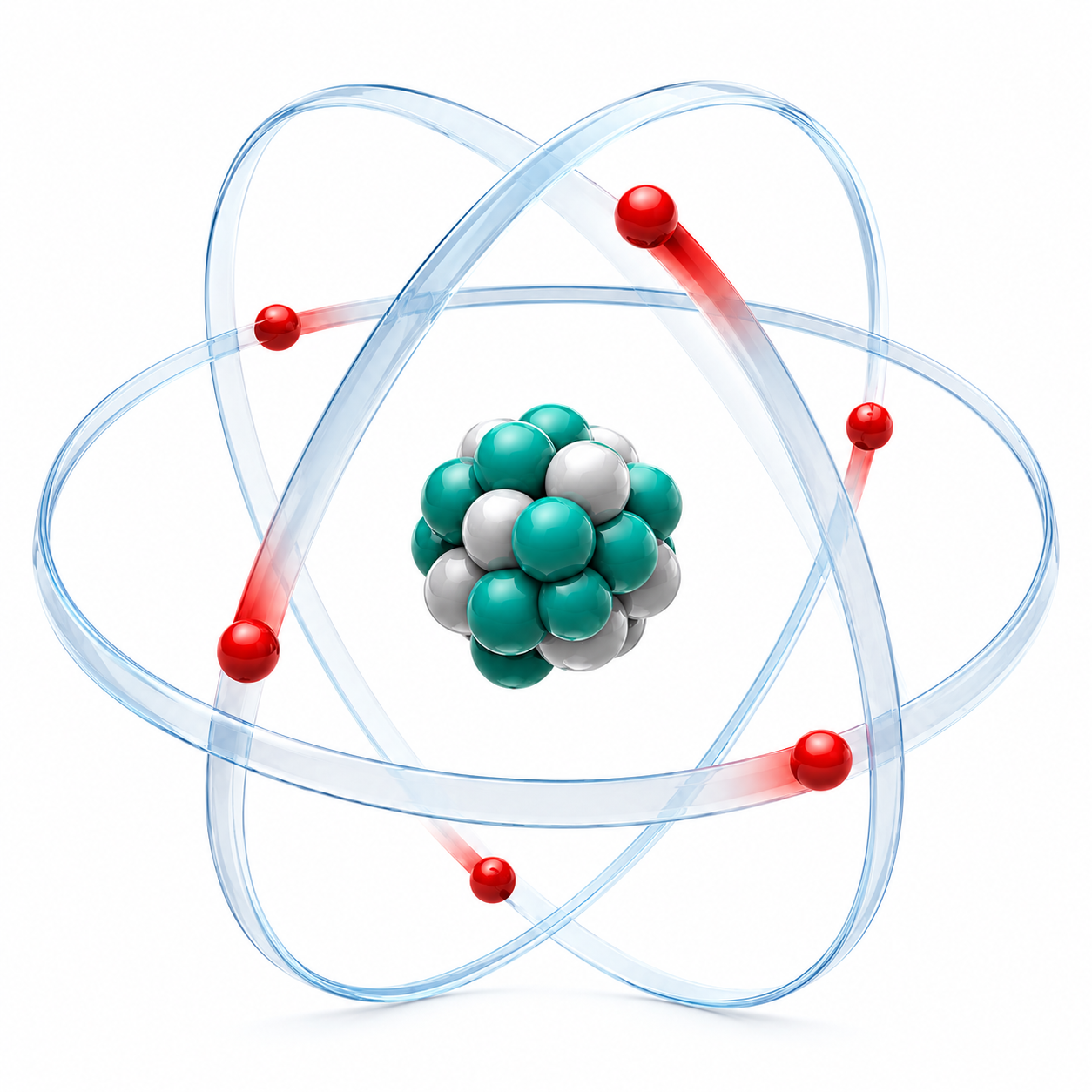
The matter comprising our universe occupies space and possesses mass, and it can assume solid, liquid, gaseous, and plasma states. Matter is built from atoms, the basic units consisting of a central nucleus surrounded by orbiting electrons. Graphic © magnetix/Shutterstock.com.
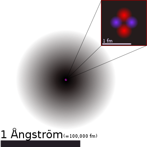
The positively charged nucleus contains most of an atom's mass in the form of positively charged protons and uncharged neutrons. Negatively charged electrons occupy regions of probability called orbitals at varying distances from the nucleus and participate in chemical reactions. The familiar image of electrons circling the nucleus like planets is a convenient simplification rather than a literal description. In a neutral atom, the number of electrons equals the number of protons, so the positive and negative charges cancel out and the atom's net charge is zero.
Elements are substances whose atoms all share the same atomic number and that cannot be broken down by ordinary chemical reactions. The periodic table currently contains 118 named elements (Grant, 2015). Six of them—carbon (C), hydrogen (H), nitrogen (N), oxygen (O), phosphorus (P), and sulfur (S), often abbreviated CHNOPS—account for the great majority of the body's mass, and calcium (Ca) is the most abundant mineral element. For biofeedback practitioners, four elements are especially relevant: calcium (Ca), chlorine (Cl), potassium (K), and sodium (Na) supply the ions that generate the physiological potentials—like the EEG—that you monitor in every session.

How does a carbon atom differ from a sodium atom? The difference lies in the number of protons in the nucleus. Carbon has 6 protons while sodium has 11, and this total defines an element's atomic number. The combined number of protons and neutrons is the mass number, which approximates but does not equal the atomic weight—the weighted average mass of an element's naturally occurring isotopes.
Ions are atoms or molecules that carry an electrical charge because they have gained or lost electrons. The biological potentials produced by cortical neurons (EEG), eccrine sweat glands (EDA), and skeletal muscles (SEMG) are all currents of ions—specifically chloride (Cl-), potassium (K+), and sodium (Na+). Understanding ions is essential because they are the currency of every biological signal you will record.
Electric Current
This section explains how electric current works, why it flows, and how the materials in its path influence its movement. These principles apply directly to both the ionic currents inside your clients' bodies and the electronic currents inside your instruments.
Charge (Q) indicates the imbalance between positively and negatively charged particles in a given place or between two locations, and it is measured in coulombs. When there is a charge imbalance between two points—say, between the two ends of a wire—negatively charged electrons flow toward the positively charged end, creating an electric current (I). This flow occurs because opposite charges attract while identical charges repel. This unit follows the electron-flow convention, describing movement from negative to positive. Most engineering texts and circuit diagrams instead use conventional current, drawn in the opposite direction from positive to negative; the underlying physics is identical and only the bookkeeping differs (Nilsson & Riedel, 2008).
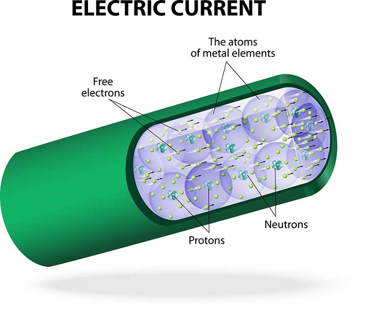
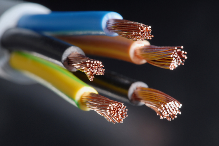
Electrons are also affected by the materials in their path. Conductors like copper allow electron movement freely, while insulators enclosing the wires—such as rubber or glass—oppose their movement. This conductor-insulator distinction matters in biofeedback: your electrode cables are conductors wrapped in insulation, and the biological signals you record must traverse both conducting and insulating tissues.
Volume Conduction and Biological Insulators
This section explains how biological signals travel through the body to reach your electrodes, and why the body's own insulating tissues can attenuate those signals. These principles directly affect the quality of recordings in every biofeedback modality.
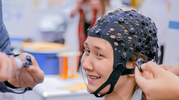
Biological signals like the EEG do not travel through wires inside the body—they travel through interstitial fluid, the fluid between cells. Signals bump their way through body fluids as a current of colliding ions (not electrons) until they reach the skin. This process, called volume conduction, is what allows clinicians to eavesdrop on cortical potentials from the scalp instead of inserting electrodes directly into the brain.
Electrodes are specialized conductors that convert these ionic biological signals into currents of electrons. Surface EEG electrodes loosely resemble an antenna, detecting the signals produced by macrocolumns of cortical neurons, but the comparison should not be taken literally.
A radio antenna captures electromagnetic waves that radiate through space, whereas an EEG electrode senses voltage changes produced by ions conducting through the adjacent tissue. The comparison to an FM radio broadcast is likewise loose, describing only the spread of a signal from a source to a distant receiver.
The brain does not transmit radio waves, and volume conduction is a near-field process, meaning the signal spreads through nearby conductive tissue rather than radiating across space (Stern et al., 2001).
However, insulation from body fat, connective tissue, and the epidermis (the outermost skin layer) interferes with ion current flow and can significantly reduce surface EMG readings. Like the rubber covering muscle electrode wiring, biological insulators block the flow of electric currents.
The difference between a conductor and an insulator comes down to how tightly an atom holds the electrons in its valence shell, the outermost energy level that takes part in conduction. Conductors such as copper hold only one or two loosely bound valence electrons that break free easily and drift as current, whereas insulators such as rubber and glass keep their valence electrons in nearly full, tightly bound shells that resist this loss (Nilsson & Riedel, 2008).
Measuring Current
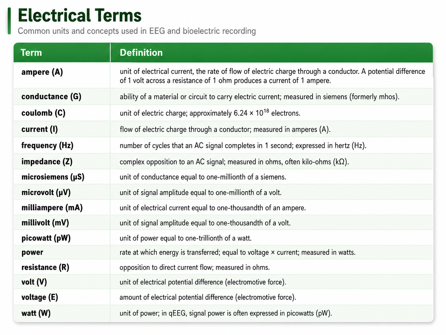
The "amount" of electric current is measured in amperes (A). A current of 1 ampere flows when 1 coulomb of charge—the charge carried by roughly 6.24 x 10¹⁸, or about 6 billion billion, electrons—passes a point in 1 second (Kubala, 2009). In biofeedback practice, the currents you encounter are far smaller—typically measured in milliamperes (mA) or even microamperes (µA).
DC and AC
This section covers the two fundamental forms of electricity—direct current and alternating current—and explains which biological signals belong to each category. Knowing the difference is essential because your instruments process DC and AC signals differently.
Direct current (DC) is the flow of electricity in one direction, driven by a difference in electrical potential. Electrons travel from the negative end of a wire, which repels them, toward the positive end, which attracts them, producing a steady one-way flow. Several biofeedback modalities—peripheral blood flow (blood volume pulse and skin temperature), respiration, and electrodermal activity—produce slowly varying signals that are recorded through DC-coupled channels because their clinically meaningful information lies at or near 0 Hz. Two qualifications are worth noting: skin temperature is a thermal quantity converted to a voltage by a transducer rather than a current in its own right, and the blood volume pulse has a pulsatile component near 1 Hz that many systems display AC-coupled. "DC" here describes how a channel is coupled, not a signal that literally never changes direction.
The electroencephalogram (EEG) contains both DC components (slow cortical potentials) and AC waveforms (delta through 40-Hz activity). BioGraph ® Infiniti blood volume pulse (BVP) display.
In contrast, an alternating current (AC) regularly reverses direction (e.g., line current completes 50 or 60 cycles per second and, because direction reverses twice per cycle, changes direction 100 or 120 times each second). The frequency of an alternating current is the number of cycles completed per second, measured in hertz (Hz). Electrical potentials detected from the cerebral cortex (EEG), heart (ECG), and skeletal muscles (SEMG) all contain AC waveforms (Kubala, 2009). Check out the YouTube video AC and DC Differences.
BioGraph ® Infiniti 60-Hz artifact display. The software uses an auto-scale feature to keep the fluctuating signal on the screen.
The movie below is a single-channel BioTrace+ /NeXus-32 display of EEG activity from 1-64 Hz broken into component delta, theta, alpha, and beta frequency bands by digital filters © John S. Anderson.
Electromotive Force (EMF)
What forces electrons to move through a circuit? Electrons flow when there is a difference in electrical potential or charge. Consider a flashlight: its battery contains negative and positive poles, and these two regions of opposite charge produce an electrical potential difference called the electromotive force (EMF) that drives the current forward.
The battery's negative pole repels electrons while its positive pole attracts them, resulting in current flow. If both poles had identical charges, electrons would stay put—no potential difference means no current and no light (Nilsson & Riedel, 2008). This same principle operates in your clients' nervous systems: differences in ion concentration across neuronal membranes create the potential differences that drive the EEG signals you record.
Electrons Drift While Electromagnetic Fields Carry the Energy
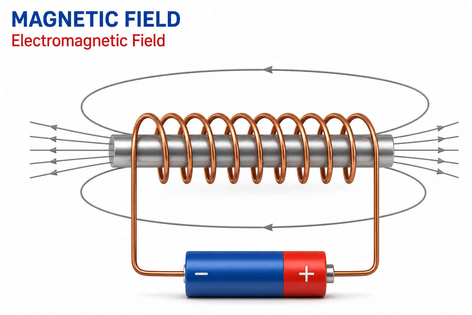
The electron-flow model used throughout this unit is a useful and largely accurate picture, but it needs one refinement. Electrons do move through a conductor, yet they travel remarkably slowly, a sluggish motion called drift velocity that amounts to only a fraction of a millimeter per second.
The bulb still lights almost instantly because the electromagnetic field, the region of electric and magnetic influence surrounding the circuit, propagates near the speed of light and delivers the energy to the bulb.
In other words, the drifting electrons are real, but the energy that powers your equipment is carried by the field that guides them, and the same principle holds for sunlight, power lines, and neurons.
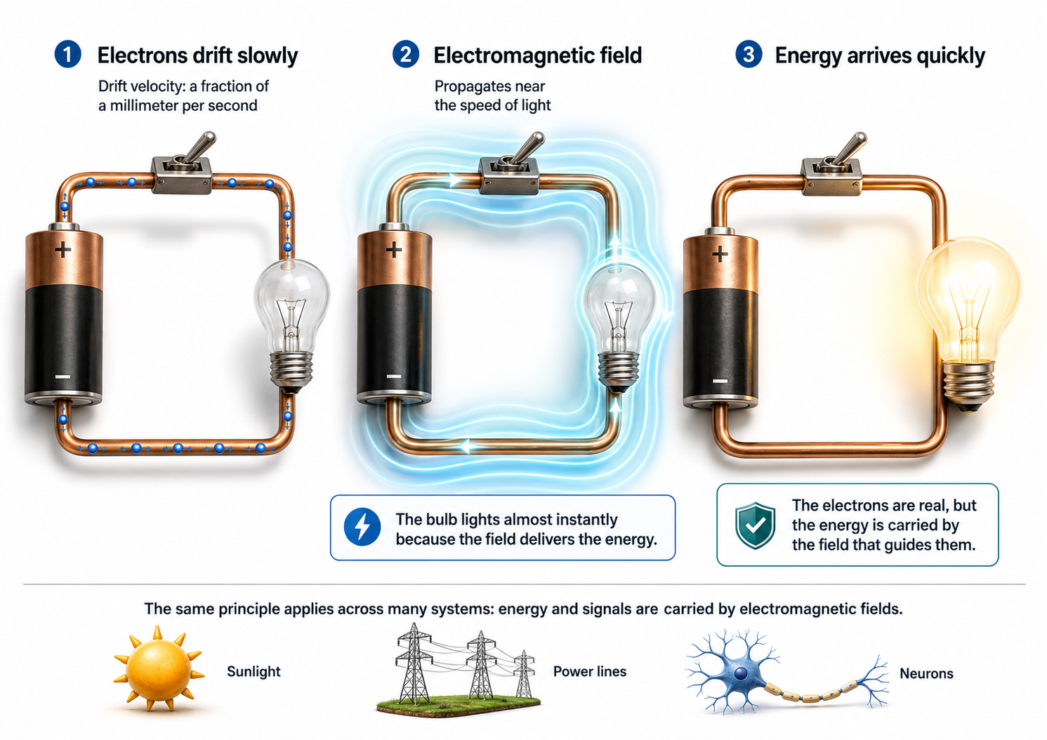
Watch the YouTube video, The Big Misconception About Electricity, for a fuller treatment.
Voltage
The pressure a battery exerts on electrons flowing through a flashlight is the voltage, measured in volts (V). A typical flashlight battery is rated at 1.5 volts, where one volt is the potential difference that gives each coulomb of charge (6.24 x 10¹⁸ electrons) one joule of energy, the joule being the standard unit of energy and work. Voltage is closely tied to a signal's strength, and the next sections trace how voltage, current, and power relate (Nilsson & Riedel, 2008).
When monitoring biological signals, you will encounter amplitudes ranging from microvolts (μV)—millionths of a volt—to millivolts (mV)—thousandths of a volt. EEG and SEMG amplitudes are measured in microvolts and are usually less than 100 μV, which underscores why sensitive amplification is so critical in clinical practice.
Some neurofeedback software expresses quantitative EEG (qEEG) signal strength in picowatts (trillionths of a watt). Be precise about what that label means. EEG power is computed as amplitude squared and therefore carries units of microvolts squared (μV2); the picowatt label follows from dividing by a reference resistance of 1 ohm, since 1 μV2 across 1 ohm equals 1 pW. The numerical value is unchanged, so picowatts here is a labeling convention rather than a measurement of true electrical power delivered by the scalp. The qEEG is a form of digitized statistical brain mapping that typically uses a montage of at least 19 channels, the number required by most normative databases, to measure EEG amplitude and power within specific frequency bins.
Watts
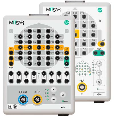
An electric current's overall power depends on both the amount of current flowing through a circuit (measured in amperes) and the electric potential driving it (measured in volts). Electric power is measured in watts (W), where one watt equals one ampere flowing across a potential difference of one volt. For example, an appliance that draws 10 amperes at 115 volts consumes 1,150 watts (Kubala, 2009). Below are 21- and 32-channel Mitsar amplifier systems featured on the NovaTech EEG website.
This relationship explains why EEG signal strength can be reported in two different ways. The signal's voltage, or amplitude, can be stated directly in microvolts, or the same signal can be described by its power, the rate at which energy is delivered, expressed in μV2 or, under the 1-ohm convention described earlier, in picowatts.
These are not interchangeable units for one quantity, because power rises with the square of amplitude, so doubling a signal's microvolt amplitude quadruples its power. Knowing which measure your software displays prevents you from misreading a fourfold change in power as a fourfold change in amplitude.
Resistance
This section covers resistance and conductance—two sides of the same coin—and explains why they matter for every biofeedback recording you perform. Understanding these concepts will help you troubleshoot signal quality problems and appreciate why skin preparation is not just a formality.
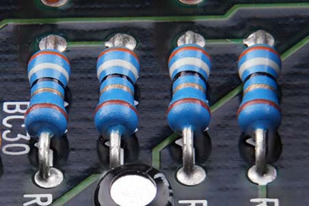
Electrons moving through a conductor encounter opposition that reduces current flow. This opposition is called resistance (R) in DC circuits and impedance (Z) in AC circuits, and both are measured in ohms (Ω). A material's resistance reflects how tightly its atoms hold their valence electrons: tightly bound electrons in nearly full outer shells leave few carriers free to move, raising resistance, whereas loosely bound valence electrons travel readily and lower it. A given conductor's resistance also rises with its length and falls as its cross-sectional area increases. In metals such as copper, resistance rises with temperature as well, but this relationship is reversed in semiconductors and in many electrolytes, including the conductive gels and pastes used in EEG recording.
▶ Mini-Lecture on Resistance and Conductance
Resistance is a practical concern in every biofeedback session, because weak biological signals must be distinguished from stronger competing signals (artifacts). Clinicians clean, abrade, and apply conductive gel to the skin when monitoring the brain (EEG) and skeletal muscles (SEMG) because dead skin, oil, and dirt behave as insulators that raise skin-electrode impedance. High and unequal impedances cost only a little signal amplitude with a modern high-impedance amplifier, but they markedly increase susceptibility to power line interference and movement artifact, which is the principal reason skin preparation matters (Kappenman & Luck, 2010).

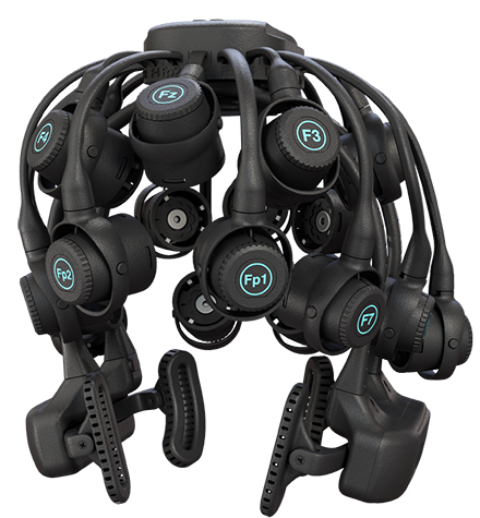
Dry electrodes, like BrainMaster's Freedom 20R, eliminate the need for time-consuming skin preparation and conductive paste application. These electrodes trade some signal quality for convenience, making them attractive for certain clinical and training applications.
Skin resistance is also a biological signal in its own right, reflecting emotional and cognitive processes. Clinicians measure skin resistance level (SRL) by passing a small alternating or direct current across the inner surface of the fingers or palm. SRL is expressed in kilohms and, when normalized for electrode contact area, in kilohm-centimeters squared (KΩ·cm2). Reported values vary widely with electrode size, recording site, and instrument; figures spanning roughly 10 to 500 KΩ are commonly cited, and any value must be interpreted against the norms supplied with your own equipment. Lower values reflect more intense sweat gland activity since the moisture and minerals in sweat reduce resistance—a principle that makes electrodermal monitoring possible.
Conductance
Resistance and conductance are mirror images of each other: resistance is the reciprocal of conductance. Where resistance measures the opposition free electrons encounter, conductance (G) indexes how easily they travel through a conductor like copper or silver. Resistance is expressed in ohms (Ω), while conductance is measured in siemens (S), the unit that replaced the older mho—ohm spelled backwards. Because the two are reciprocals, a resistance of 100 KΩ corresponds to a conductance of 10 μS. Skin conductance is one index of eccrine sweat gland activity, making it a widely used measure in biofeedback and psychophysiological research.
Ohm's Law
This section introduces Ohm's law, the fundamental equation governing the relationship between voltage, current, and resistance. This relationship explains why skin preparation improves recordings and why amplifier design matters for signal quality.
Ohm's law states that the "amount" of current (I) flowing through a conductor equals the voltage (E)—the "push"—divided by the resistance (R). These values are measured in amperes, volts, and ohms, respectively (Nilsson & Riedel, 2008). The law can be restated to find any value in a DC circuit: Voltage (E) = current (I) x resistance (R). For example, 10 volts = 2 amperes x 5 ohms. Check out the YouTube video MAKE Presents: Ohms Law.
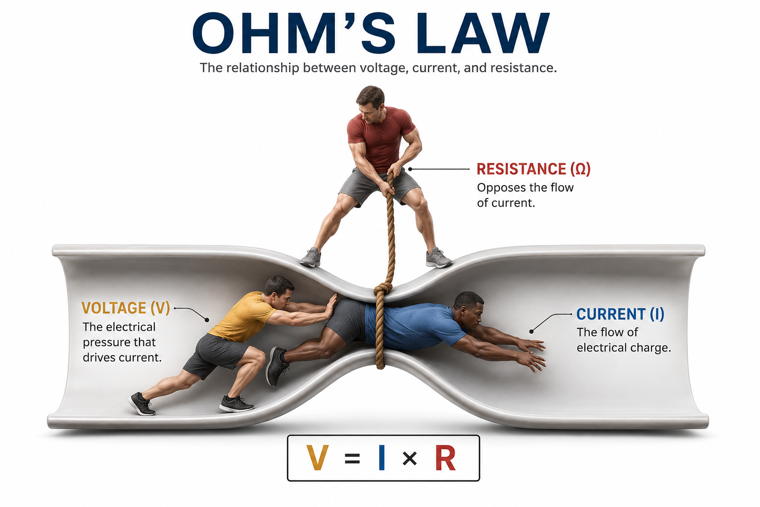
Ohm's law is valuable because it explains two strategies that help biofeedback instruments recover adequate voltages. First, since voltage (E) = current (I) x resistance (R), the voltage developed across any element of a circuit grows with that element's resistance. Hardware designers exploit this relationship: the skin-electrode interface and the amplifier input together form a voltage divider, so when the amplifier's differential input impedance is very large compared with the skin-electrode impedance, nearly the entire EEG voltage is dropped across the amplifier input instead of being lost at the electrode. Note the distinction: a high input impedance does not create additional voltage, it preserves the voltage the brain already generated, and that preserved amplitude is what allows genuine EEG activity to be separated from artifacts.
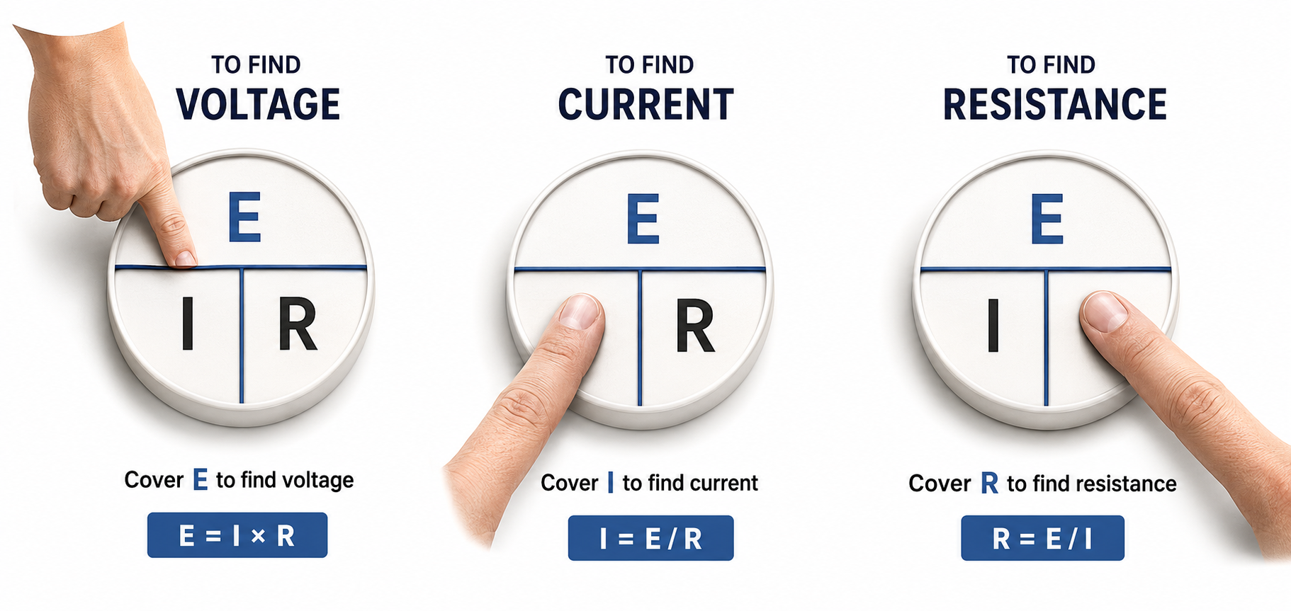
Second, we can restate Ohm's law from the standpoint of current: if current (I) = voltage (E) / resistance (R), then lowering resistance increases the current a given voltage can drive. Skin abrasion and conductive gel or paste lower the resistance and impedance of the skin-electrode interface. It is worth being precise about why this helps. Modern EEG amplifiers present such high input impedance that they draw almost no current from the client, so the benefit of skin preparation is not that more current reaches the amplifier. Rather, lower and better matched impedances reduce the voltage lost at the interface, preserve common-mode rejection, and lower the recording's susceptibility to power line and movement artifact (Kappenman & Luck, 2010).
Impedance
This section addresses impedance—the AC counterpart to resistance—and explains why impedance testing is one of the most important quality-control steps in every biofeedback session. Poor impedance management is among the most common causes of inaccurate recordings.
In AC circuits, current periodically reverses direction, and the rate of this reversal is the signal's frequency, the number of cycles completed each second, measured in hertz (Hz). When an AC signal travels through a circuit at a given frequency, it encounters a complex form of opposition called impedance (Z), measured in ohms (Ω). In EEG recording, the skin-electrode interface presents an impedance in series with the amplifier input. High impedance costs a modest amount of signal amplitude, but its more serious effect is to degrade common-mode rejection and invite interference, so artifact typically grows faster than signal is lost (Kappenman & Luck, 2010).
Why is impedance called "complex" rather than simply resistance? A DC circuit experiences resistance as a single fixed value, but an AC circuit adds a second, frequency-dependent component called reactance, the opposition that appears when a circuit stores and then releases energy as the current alternates. Impedance is the combination of resistance and reactance.
Most of the reactance at the skin-electrode interface comes from capacitance, the ability of two conductive regions separated by a thin insulator to store electrical charge, which occurs naturally where electrode metal, electrolyte gel, and skin layers sit close together.
Because reactance changes with frequency, the same electrode site can oppose a slow signal more than a fast one, which is one reason low-frequency and infra-slow recordings are so demanding.
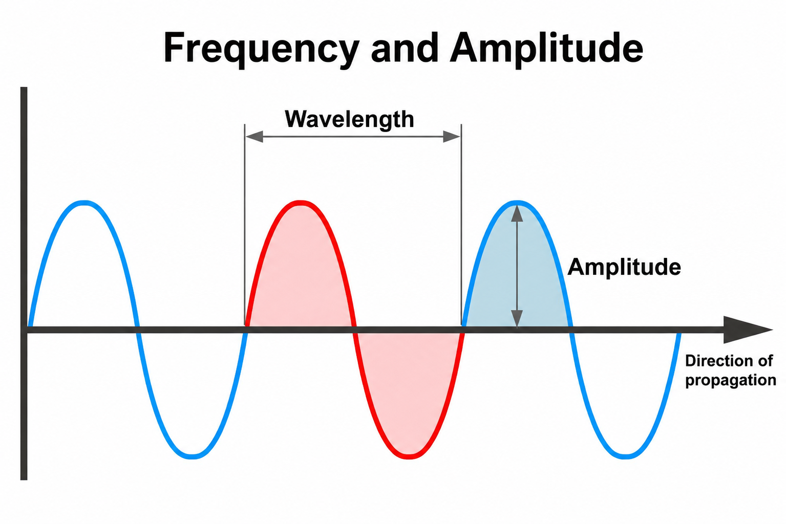
Wavelength and frequency share an inverse relationship. Frequency refers to the number of complete wave cycles that pass a given point per unit of time, typically measured in hertz. Because wave speed remains constant for a given medium, a longer wavelength means fewer cycles can pass a fixed point each second, resulting in a lower frequency. Conversely, a shorter wavelength allows more cycles to pass in the same amount of time, producing a higher frequency. This relationship is expressed mathematically as speed equals frequency multiplied by wavelength, so if speed is held constant, frequency and wavelength must change in opposite directions.
Clinicians perform an impedance test to verify that they have correctly cleaned and abraded the skin and applied electrodes with sufficient gel or paste (Andreassi, 2007). Excessive impedance means that a weak biological signal must compete at a disadvantage with false electrical signals like power line artifacts. In severe cases, the electroencephalograph may display power line fluctuations instead of cortical activity—rendering the session clinically useless.
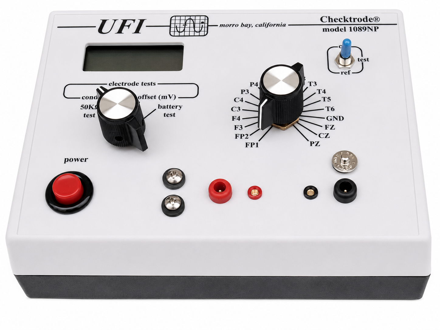
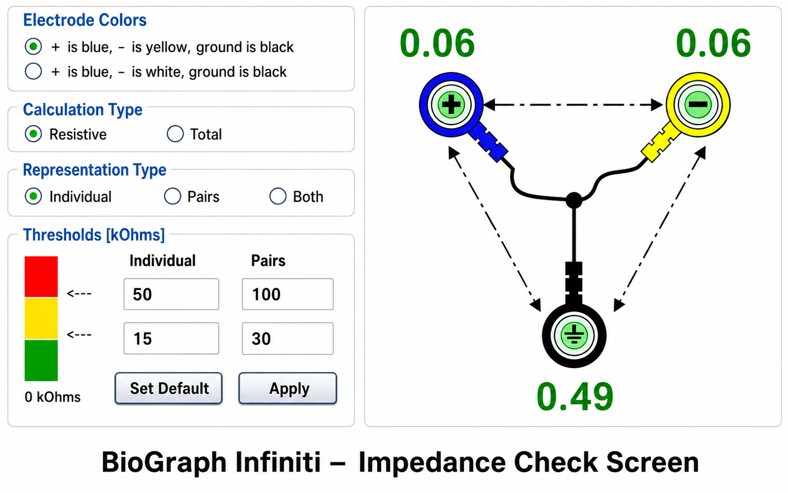
Impedance can be measured by passing a very small alternating current through pairs of electrodes using a separate impedance meter or through software integrated with the data acquisition system. After positioning all electrodes, clinicians should check impedances or offsets using methods appropriate for their equipment. Electrodes that show excessive values should be reapplied after re-preparing the site.
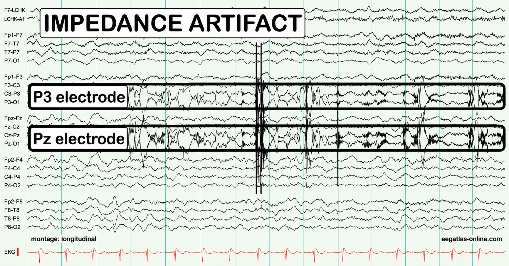
Unless skin-electrode impedance is low (under 5 KΩ for research and 20 KΩ for training) and balanced (within 1-3 KΩ between sites), diverse artifacts—including 50/60 Hz noise and movement artifact—can contaminate the EEG signal, as seen in the P3 and Pz electrodes in the recording below.
When impedances at two sites are unequal, the resulting signals will appear to have different amplitudes when they reach the amplifier, regardless of actual values, and unbalanced impedance will also increase DC offset values through the battery effect, in which each electrode-electrolyte junction acts like a small battery and adds a standing voltage to the recording.
When a clinician fails to ensure low and balanced impedances at the start or during a training session, feedback regarding signal amplitude within specific frequency bands will be inaccurate, and the wrong thresholds may be selected. This can undermine an entire course of treatment.
Michael and Lynda Thompson provided an example of an impedance problem that developed during a session because a hyperactive child scratched his ears, resulting in high and imbalanced impedances. Following corrective action that restored acceptable impedance values, high-beta activity (24-32 Hz) declined from 10-15 to 4 μV, gamma activity (45-58 Hz) declined below 2 μV, and SMR and beta activity returned to previous session values (Thompson & Thompson, 2015, p. 66).
DC Offset
DC offset is a standing voltage measured at an electrode before any biological signal is considered. It arises mainly at the junction between the electrode metal and the electrolyte gel, where ions cross the interface and create a small voltage called a half-cell potential, the potential difference produced at a single electrode-electrolyte contact. This is the same phenomenon described above as the battery effect, since each junction behaves like a weak battery.
Several other factors add to the measured offset, including the electrode and gel materials, interactions with the skin, environmental conditions such as humidity and temperature, and sweat gland activity related to stress level.
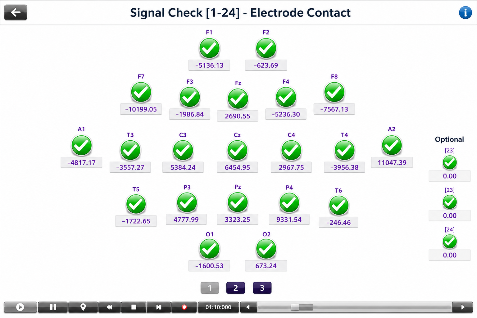
Acceptable DC offset limits are set by the equipment manufacturer rather than by a universal standard, so consult your own system's documentation. As one representative example, some systems specify that offsets be consistent across all sensors and below 25,000 μV (25 mV), ideally below 10,000 μV (10 mV). In every system, inconsistent offsets across channels signal poor electrode contact or mismatched materials and should be corrected before proceeding.
Ohm's Law for AC Circuits
We can extend Ohm's law to AC circuits by substituting impedance (Z) for resistance. The revised expression is voltage = current x impedance (E = I x Z), meaning that voltage is the product of a current flowing across an impedance. In actual units, 50 volts = 10 amperes x 5 ohms. One qualification matters: impedance is a complex quantity with both a magnitude and a phase angle, so this simple multiplication applies to magnitudes, and a complete AC analysis must also account for the phase shift the reactive component introduces. This AC version of Ohm's law governs the relationship between the EEG signal and the impedance it encounters at every point between cortex and computer.
Open and Closed Circuits
This section covers circuit integrity—the difference between open and closed circuits—and explains the practical tests clinicians use to verify that their equipment is functioning correctly.
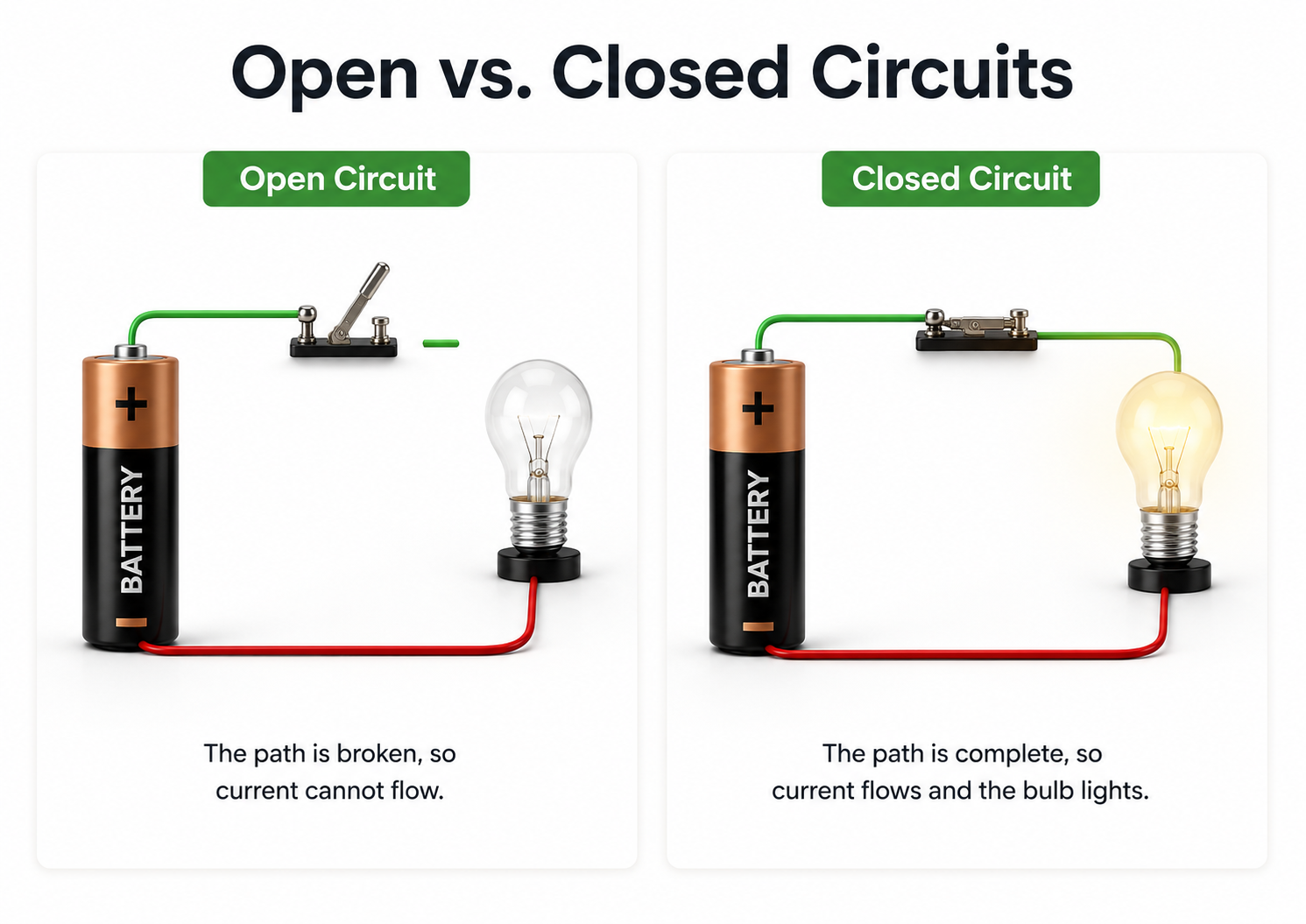
Broken electrode cables are a significant cause of equipment malfunction since they prevent electron movement. Clinicians perform a continuity test to check whether a cable is damaged by sending an AC signal down the cable with an impedance meter to measure opposition to current flow. If there is a break, there is no continuity, and the circuit is described as open—impedance will be effectively infinite since current cannot flow across the gap.
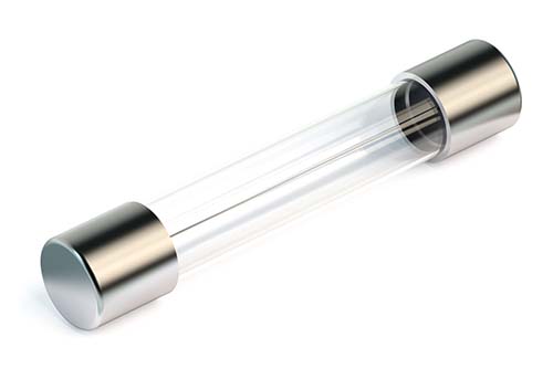
A Blown Fuse Illustrates an Open Circuit
A fuse contains a filament designed to melt and create an open circuit when the current exceeds safe values, protecting downstream components from damage.
If the cable is free of breaks (continuous), the circuit is described as closed instead, and impedance will approach 0 Kohms since the current can easily travel through the circuit.
Behavioral Tests Check Circuit Performance
Behavioral tests, also called tracking tests, go beyond continuity testing to evaluate the performance of the entire data acquisition system. For example, when monitoring EEG activity, a clinician can test the complete signal chain—EEG sensor, differential amplifier, gain amplifier, cable, encoder, and computer—by asking a client to close and then open the eyes. If the computer display mirrors these actions (showing alpha blocking when the eyes open and alpha return when they close), the behavioral test is passed, confirming the system is working end to end.
Short Circuit
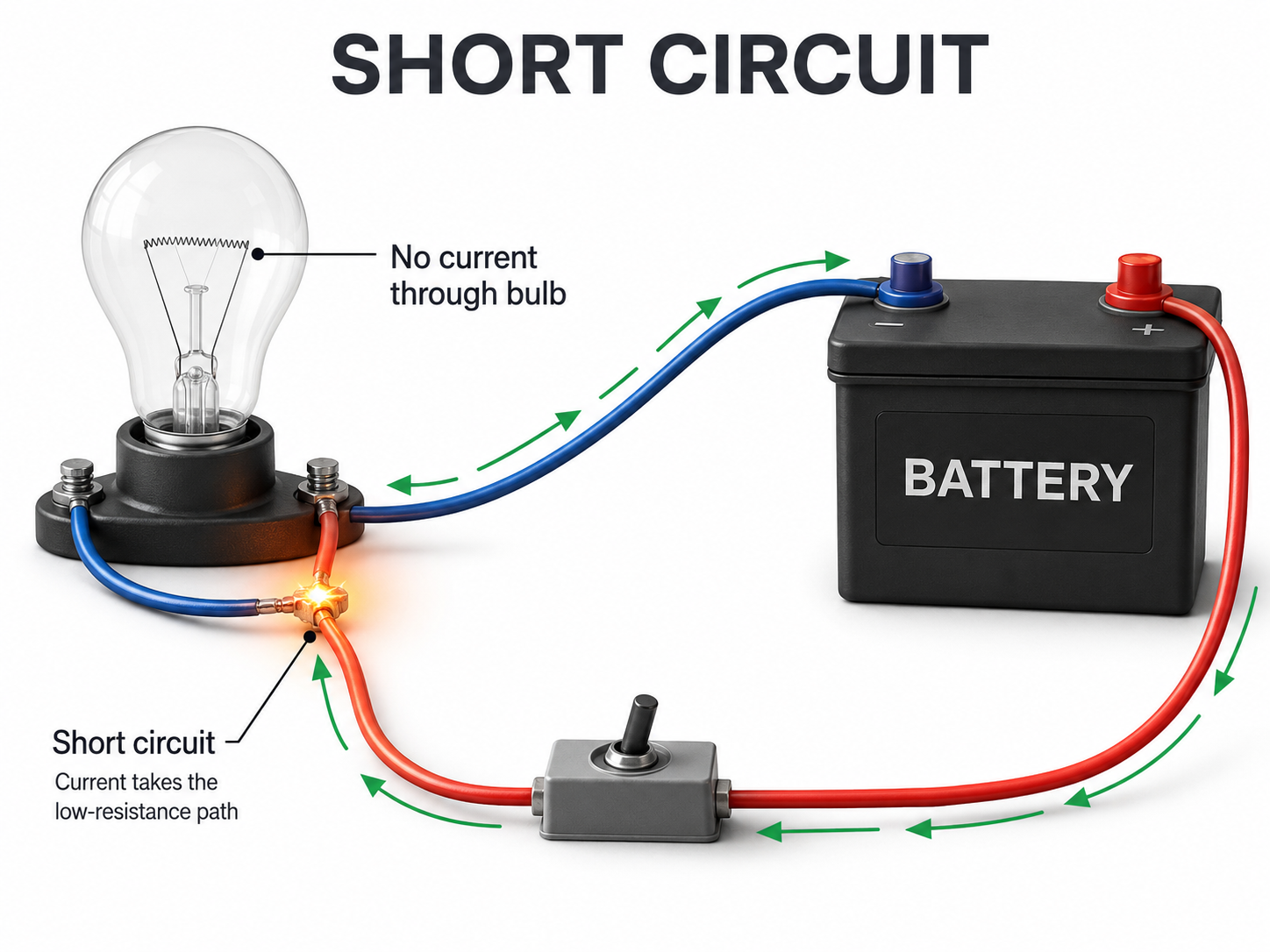
A short circuit results when an unintended connection is made between two points of a circuit, creating a new path with lower resistance than the original. This path should measure close to 0 Kohms on an impedance meter, and the reduced resistance draws electrons through the short, potentially increasing current flow to levels that can melt circuitry and injure clients (Nilsson & Riedel, 2008).
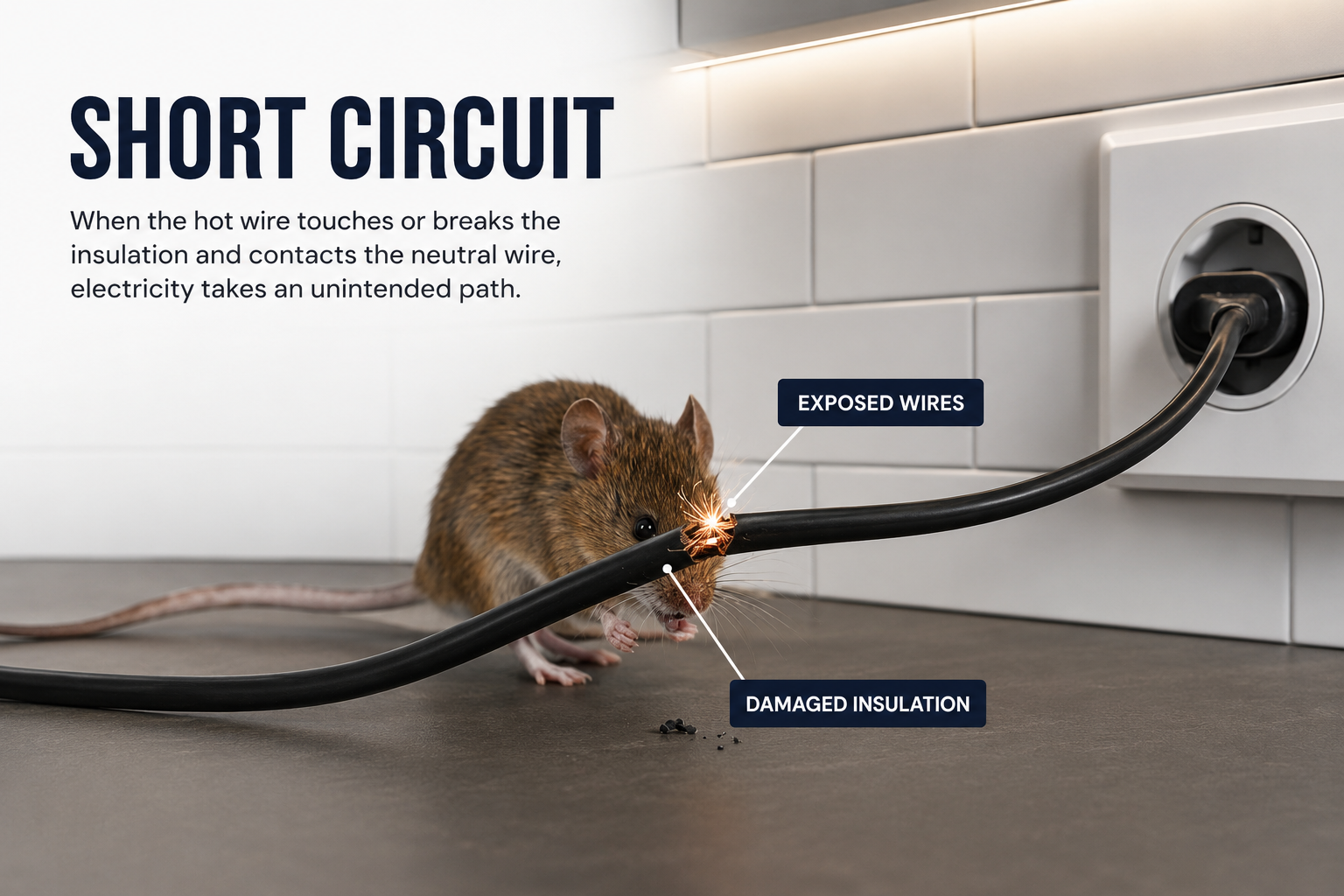
Visualize a bare wire inside an electroencephalograph touching its metal case. The AC powering this equipment could leak through the metal case and injure anyone touching the surface—a scenario that underscores why the safety precautions discussed later in this unit are not optional.
Preventing Signal Contamination
Physiological signals are remarkably small compared to surrounding electromagnetic "noise," and they must be amplified before they can be distinguished from background interference. The quality of the connections between your client and the recording device—including the skin surface, conductive gel or paste, sensors, and connecting wires—determines the quality of the signal you gather. Poor-quality connections, regardless of the cause, produce contaminated information that compromises clinical decision-making.
Matter is composed of atoms containing protons, neutrons, and electrons; ions are charged atoms that carry biological signals through the body via volume conduction. Current is the movement of electrons (or ions) through a conductor, voltage provides the "push" that moves current, and resistance/impedance opposes current flow. Ohm's law (E = I x R) describes the relationship between these three quantities and explains both amplifier design and skin preparation practices. Clinicians must ensure low and balanced skin-electrode impedance to obtain accurate recordings, and must verify circuit integrity through continuity and behavioral tests to rule out equipment malfunction.
Matter is built from atoms whose positively charged nuclei are balanced by orbiting electrons, and a charged atom or molecule is an ion. Biological signals reach the scalp as currents of ions moving through interstitial fluid, a near-field process called volume conduction, while the hardware that records them runs on currents of electrons. Current is measured in amperes, potential difference in volts, and power in watts, where one watt equals one ampere at one volt. Ohm's law ties these together: current equals voltage divided by resistance. Resistance describes opposition in DC circuits and impedance, the combination of resistance and frequency-dependent reactance, describes it in AC circuits, and both are measured in ohms.
EEG amplitude is reported in microvolts while EEG power is amplitude squared, reported in microvolts squared or, by a 1-ohm labeling convention, in picowatts.